EXFO CableSHARK P3 VF/DSL Cable Qualifier User Manual
Page 99
CableSHARK P3 User Guide
87
8.2.2.1 Testing Cables with the Manual TDR
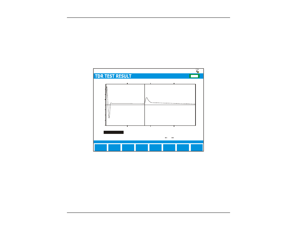
Figure 8.2.2.1A shows an example of a MANUAL TDR test result on a 2000-ft cable with an open cable end,
with the correct VOP setting and proper pulse width selected. The large pulse near 0 distance is the sent
pulse, the reflected pulse near 2000 ft is the reflection coming from the open end of the cable. The
CableSHARK will attempt to place the cursor at the bottom of the rising edge of the reflected pulse. The user
can choose to move the cursor or marker from where the CableSHARK has placed them.
Cursor position =
Marker position =
Cursor / Marker Delta =
0.0
1250.0
2500.0
5000.0
3750.0
ZOOM IN
VERT
MAIN
MENU
E
F
CHG
-1.000
-0.750
-0.500
-0.250
0.000
0.250
0.500
0.750
1.000
1998.7
0
1998.7
Pulse Width:
ft
ft
300 ns
ZOOM IN
HORIZ
SELECT
MARKER
MORE
AUTO
REPEAT
End of cable detected at 1998 ft. DBRL = 33.8+
Cursor position =
Press or to move cursor
(TIP - RING)
F
IGURE
8.2.2.1A
-
R
UNNING A
M
ANUAL
TDR
T
EST WITH THE
C
ABLE
E
ND
O
PEN
Typically any fault that produces a positive reflection indicates a high impedance. Some examples of high
impedance faults include end of cable, end of bridge tap, or an open circuit.
Figure 8.2.2.1B shows the MANUAL TDR test result on the same cable of Figure 8.2.2.1A with the cable end
shorted, with the same VOP setting and pulse width selected. Please note that the reflected pulse is of
opposite polarity to the sent pulse.