Appendix b loop characteristics – EXFO CableSHARK P3 VF/DSL Cable Qualifier User Manual
Page 269
CableSHARK P3 User Guide
257
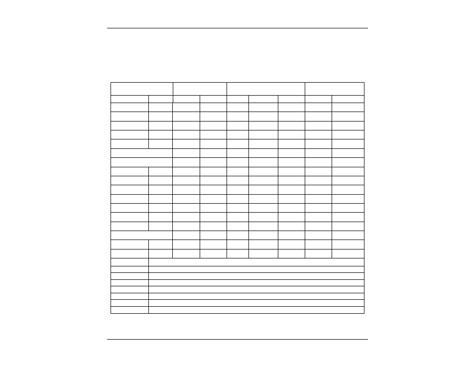
Appendix B Loop Characteristics
Wire Gauge
Capacitance
Resistance
Attenuation @ 300
kHz
mm AWG
nF/km
nF/mi
Ω
/km
Ω
/kft
Ω
/mi
dB/km dB/mi
(0.253) 30 40 64.4
677
206 1090
0.30 PE
40
64.4
494
150
792
0.32
PE 28 40 64.4 409
125 658 21.0
0.40
PE
50 80.5 280
84.4 451 14.2
(0.405) 26
PIC
51.6
83.0 273
83.1 439
23.5
0.50
DW10
50.9 82.0 181
55.1 291
0.50 DUG
55
88.5
179
55.6
288
0.50
PE
50 80.5 179
54.5 288 10.1
(0.511) 24
PIC
51.6
83.0 172
52.3 276
18.0
0.60 PE
40
64.4
123
37.5
198
8.6
0.63 PE
45
72.4
113
34.5
182
(0.644) 22
PIC
51.6
83.0 108
32.9 174
14.1
0.70 PE
40
64.4
90
27.5
145
0.80 PE
40
64.4
69
21.0
111
7.1
0.90 DW12
51.1
82.3
55.5 16.9
89.3
0.90
PE
40 64.4 55 16.8 88.5
(0.912) 19
PIC
51.6
83.0 53.8
16.4 86.6
10.0
NOTES:
( ) = AWG conductor diameter
→
(mm) = not a normal metric size
PE = metric Polyethylene insulated cable
PIC = AWG Polyethylene insulated cable, sometimes called "plastic insulated cable"
as contrasted to older pulp or paper insulated cable.
PVC = Polyvinyl chloride insulated cable
DW = European drop wire, overhead/aerial
DUG = European underground drop cable
Metric & AWG Wire Gauges: R & C (0Hz/DC, 20
°C or 70°F)