EXFO CableSHARK P3 VF/DSL Cable Qualifier User Manual
Page 22
VF / DSL Cable Qualifier
10
Figure 3B - A Pulse Reflection indicates a load coil at 500 ft (152 m)
TDR’s can use various methods of testing to determine the location of problems along the length of the cable
under test. Impedance is a major player. The TDR equipment looks for a change in impedance which could
be caused by improper installation, cable damage (caused by water, etc.), end of cable, and a bridged tap.
The magnitude of the impedance changes determines the amplitude of the reflection.
There is a direct relationship between voltage pulse width sent down the cable and the distance that it travels
along the cable. The smaller the pulse, the less the energy it contains, and therefore, the distance that it
travels along the cable is less. Voltage pulses of greater width travel further distances. When using this
technique, it is best to start testing with voltage pulse of small width and to work up to pulses of larger width.
Voltage pulse width is typically measured in nanoseconds.
Several factors affect the operation of TDR devices and the results they display. As mentioned earlier in this
section, VOP, or Velocity of Propagation is a very important value to know in determining the distance to an
impairment. VOP represents the speed at which energy travels through a medium. In the case of xDSL, the
medium is a copper twisted pair. VOP is measured as a percentage of the speed of light in a vacuum. Users
of TDR’s may see the VOP expressed as 0.66 or 66%; both are acceptable.
VOP is an extremely important parameter. It must be correct, as any deviations may give the user false
readings. Most cable manufactures will indicate the VOP for their particular cable. The VOP depends upon
cable diameter, material out of which the cable is made, and on impurities in this material.
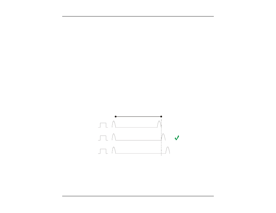
1000 ft (300 m)
VOP = 62%
VOP = 64%
VOP = 66%
X
X
Figure 3C – Selecting the correct VOP means knowing the correct distance
When using the TDR technique, the cable under test should not be terminated. Cables that are terminated
absorb most or all of the energy pulse sent down the cable which, in turn, means that no energy is reflected
back to the TDR device. When using the CableSHARK’s TDR function, ensure that the far end of the cable
is configured as an OPEN or SHORT circuit.