Frequency response test setup – EXFO CableSHARK P3 VF/DSL Cable Qualifier User Manual
Page 84
VF / DSL Cable Qualifier
72
Here are some examples of typical VOP values for various telephone cables, given for insulation type and
wire gauge / size. :
Pulp
AWG 22 0.6 mm VOP = 0.68 (102 m/
μs)
AWG 24 0.5 mm VOP = 0.67 (100 m/
μs)
AWG 26 0.4 mm VOP = 0.66 (99 m/
μs)
PIC
AWG 19 0.9 mm VOP = 0.72 (108 m/
μs)
AWG 22 0.6 mm VOP = 0.67 (100 m/
μs)
AWG 24 0.5 mm VOP = 0.66 (99 m/
μs)
AWG 26 0.4 mm VOP = 0.64 (96 m/
μs)
Jelly
Filled
AWG 19 0.9 mm VOP = 0.68 (102 m/
μs)
AWG 22 0.6 mm VOP = 0.62 (93 m/
μs)
AWG 24 0.5 mm VOP = 0.60 (90 m/
μs)
AWG 26 0.4 mm VOP = 0.58 (87 m/
μs)
Polyethylene
VOP = 0.66 (99 m/
μs)
Polypropylene
VOP = 0.66 (99 m/
μs)
Teflon
VOP = 0.67 (100 m/
μs
EDIT /
SELECT
CABLE
TESTS
MAIN
MENU
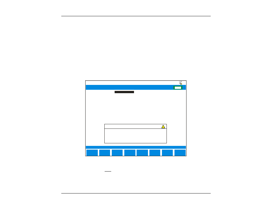
Test Typ e:
Result Scaling:
Max. C ap. Imbalance (%):
F1 Length:
Cab le Type:
VOP:
VOP (m/us):
Cap acitance nF/mi:
Resistance ohm/mi:
Attn at 300kHz dB/mi:
ADSL - 2208 kHz
10
0
24 AWG PIC
0.660
198
83.0
277.0
18.0
E
F
CHG
FREQUENCY RESPONSE TEST SETUP
SINGLE EN D
WA RNING
For Single End test please ensure that th e ca ble t o be
tested is not terminated at t he far end.
Not e: telephone cables may have dan gerou s A.C. o r D. C.
volta ges on them, theref ore caution should be taken when
!
SELECT
PREVIOU S
SELECT
NEXT
Figure 8.1.1B – Single End Frequency Response Test Setup Menu
If the AUTO CABLE TYPE is NOT selected, the following settings are available. These are necessary to
provide the user with the most accurate results.