Lake controller tutorial 39 – Lab.gruppen PLM 20K44 User Manual
Page 44
Lake Controller Operation Manual Rev 1.5.4
Lake Controller Tutorial
39
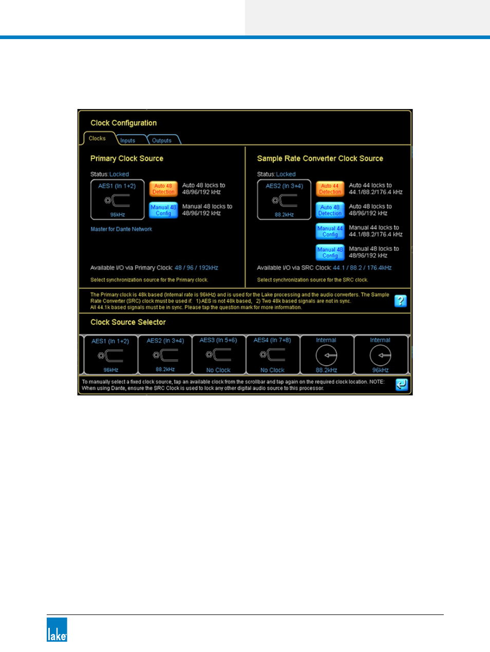
an internal clock operating at 96 kHz. You can choose to use any available external clock source using the
interface provided by the clock source configuration window.
Figure 4-22: LM 44 Digital Clock Configuration
The current Primary Clock Source is shown on the top left of the screen, and the current Sample Rate
Converter Clock Source is shown on the top right. You can choose any available clock source using the
Clock Source Selector scroll bar at the bottom of this window. The Inputs/Outputs tab are available on some
products providing quick access to set unique digital clocks for specific inputs and outputs.
Please refer to each product’s Operational manual for further details on clocks, clock source priorities,
sample-rate converters, and signal processing latency the product.
The INPUT CONFIGURATION pop-out window allows flexible routing of all available inputs to each Input
Mixer channel along with a four-level auto-select priority allocation for each input, as shown in Figure 4-23.