Lake controller tutorial – Lab.gruppen PLM 20K44 User Manual
Page 43
38
Lake Controller Operation Manual Rev 1.5.4
Lake Controller Tutorial
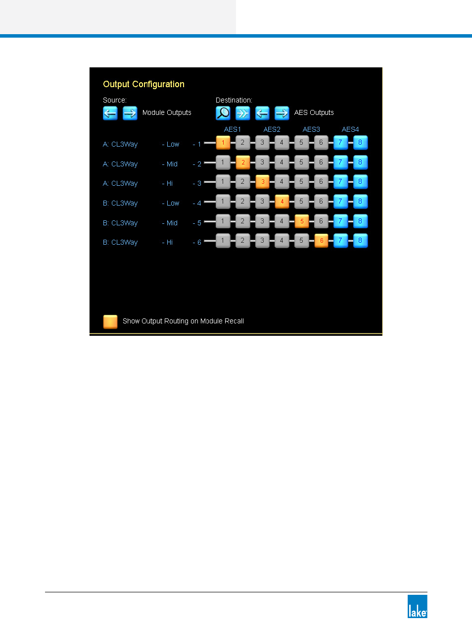
Figure 4-21: LM 26 Output Configuration
The Output Configuration window provides the ability to route any physical input or Module output to any
available analog or digital output on the device. The arrows below the source and destination labels allow
selection and mapping of all available I/O.
LM Series devices provide the ability to route any of the eight the Input Router Outputs directly to any
output. This allows fail-over input switching to be configured for pass-thru / format conversion purposes. For
instance, an input router can be configured for fail-over to Analog if AES input fails, and the whichever audio
is used can be passed through to Dante (or any other output type). For further information, please refer to
section 21.1.
5. Tap the blue EXIT/RETURN button in the bottom right to return to the I/O CONFIG page.
The left side of the I/O CONFIG summary screen provides both clock and INPUT CONFIGURATION func-
tions along with other Frame specific functionality. Status information is provided, and zoom icons open
pop-up windows for access to configuration parameters.
Lake devices have sophisticated digital clocking systems, allowing selection between internal and external
clock sources at all standard audio sample rates. By default, all Lake devices (except the MY8-LAKE) use