Modules menu reference 143 – Lab.gruppen PLM 20K44 User Manual
Page 148
Lake Controller Operation Manual Rev 1.5.4
Modules Menu Reference
143
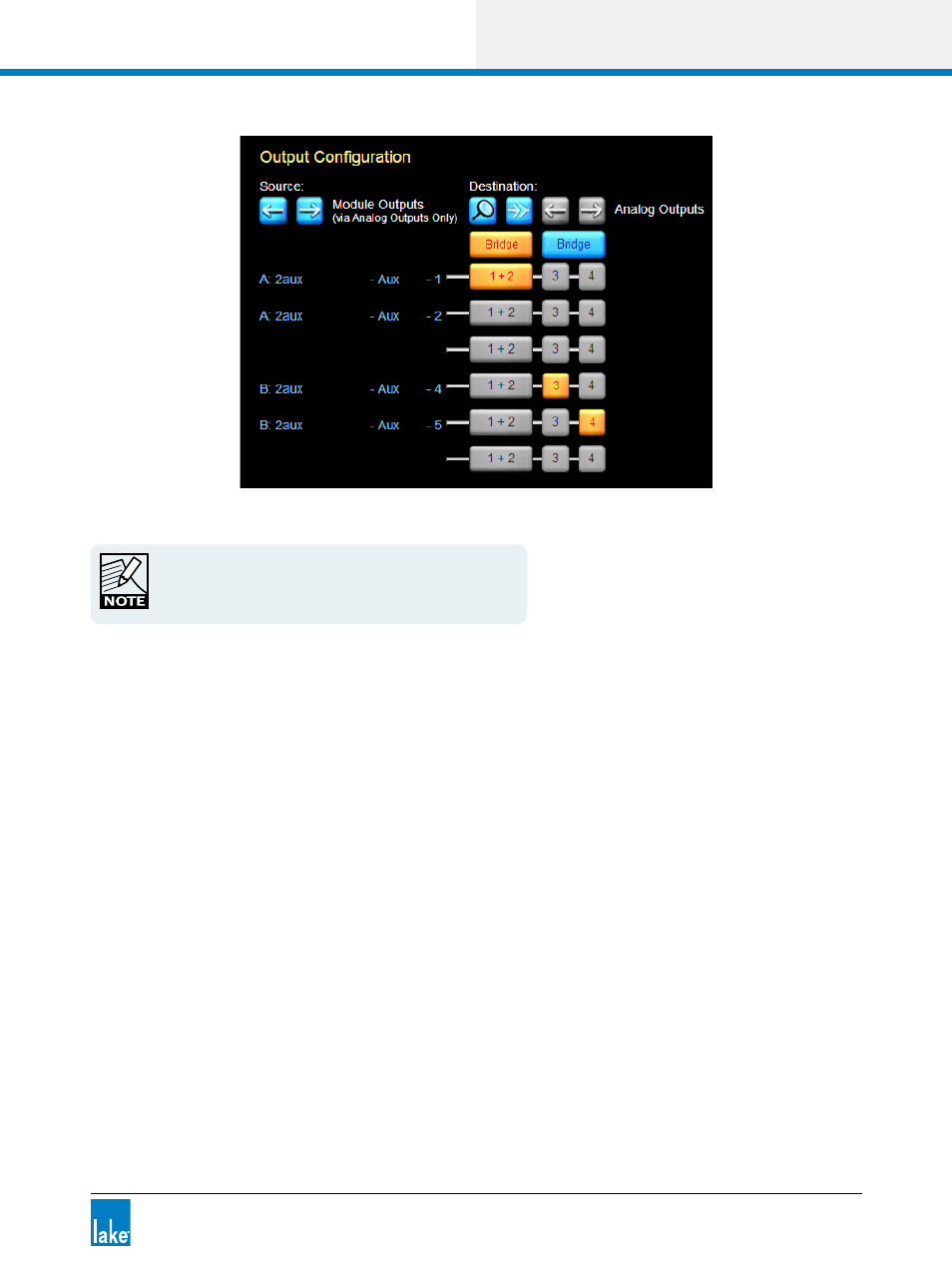
Figure 8-26: Bridge Mode (Lake-enabled amplifiers only)
When Bridge Mode is activated, CLASS 3 WIRING is
required. Please refer to the Operation Manual for additional
wiring information.
8.2.9 Latency Match
This button is available on all devices except MY8-LAKE. It is blue when disabled and orange when enabled.
This feature adds additional latency to the output signal to align latency with PLM Series devices.
LATENCY MATCH is based on the following criteria:
▸
Input types for all devices are identical (Analog or AES only).
▸
Input sample rates for all devices are identical where AES inputs are being used.
▸
Outputs are set to analog.
For any other scenarios, the appropriate delay adjustments must be made manually.
8.2.10 Technical Data
The technical data screen is displayed by tapping TECHNICAL DATA (F5) on the I/O CONFIG button bar for
the LM Series, PLM Series and MY8-LAKE devices.