Lake-enabled amplifier reference 245 – Lab.gruppen PLM 20K44 User Manual
Page 250
Lake Controller Operation Manual Rev 1.5.4
Lake-enabled Amplifier Reference
245
The channels are presented in Module output order (e.g. low, mid, high). If a Module output is assigned to
more that one power output channel then this is displayed accordingly (e.g. low, low, mid, high).
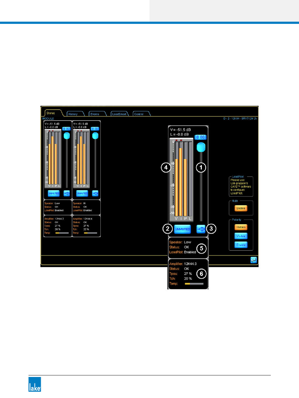
The amplifier’s meters are reproduced as vertical bar graphs. Each channel strip provides an attenuation
fader, phase reverse button, and mute button. Additional identity and status information concerning the
output channel and connected loads is shown below in two data blocks. To the right of the channel strips,
a column of control buttons provide options for displaying and enabling the mute and polarity buttons on
individual channels.
Figure 20-5: Status Tab Speaker and Power Output Channel Status