Lake controller tutorial – Lab.gruppen PLM 20K44 User Manual
Page 37
32
Lake Controller Operation Manual Rev 1.5.4
Lake Controller Tutorial
4.3.2 Module Icons
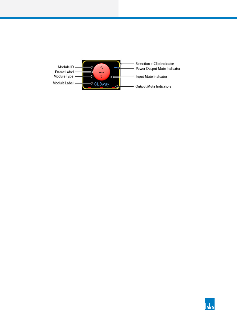
Each Module icon provides configuration information as shown in Figure 4-11.
Figure 4-11: Module Icon Components
▸
Module ID - Identifies a particular Module within the device, represented by this icon.
▸
Frame Label - Identifies the Frame (device) associated with this icon by a user-defined label that also
appears on the front panel of the device.
▸
Module Type - Identifies the number of output channels or an abbreviation of a Module type description
(MEq for a Mesa EQ Module).
▸
Module Label - User-defined label that describes the Module’s use or speaker type.
▸
Module Selection and Clip Indicator - The Module icon border is yellow to indicate the Module is
selected. If it flashes red, a channel on that Module is clipping.
▸
Power Output Mute Indicator (Lake-enabled amplifiers only) - A red bar indicates the power output
channel is muted; a blue bar indicates it is unmuted. This indicator appears on the Module from where
the channel is routed.
▸
Input Mute Indicator - If the central round part of the icon is red, the input is muted; if the icon is blue,
the input is not muted.
▸
Output Mute Indicators - Displayed as small red bars when the outputs are muted and are absent if
unmuted. The number of mute indicators depends on the number of output channels in the selected
Module type.
▸
Module Label - Displays the label for the Module, in this case a default Classic 3-Way. For further
details on Module label abbreviations and an explanation on Module types, please refer to chapter 9.
4.3.3 Selecting and Moving Icons
Multiple icons may be selected (via the MODULES, GROUPS, PAGES, and ICON CONTROL menus),
providing a faster solution to graphical arrangement of the work area. For example, multiple icons can be
dragged back to the scroll bar, moved around on screen, or dragged to another page tab.