Analyzer plug-in 211 – Lab.gruppen PLM 20K44 User Manual
Page 216
Lake Controller Operation Manual Rev 1.5.4
Analyzer Plug-in
211
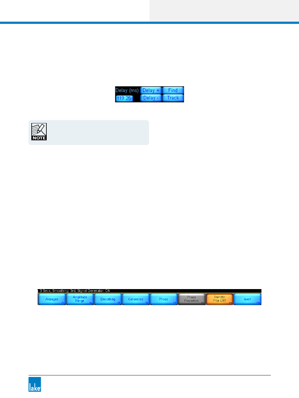
18.4.4.2 Delay Controls
The Delay controls are grouped together at the top of the screen as shown in Figure 18-13 when Transfer
mode is selected. These controls are used to provide signal alignment between the reference and measure-
ment signals for transfer function measurements.
Figure 18-13: Transfer function delay controls
Delay must be adjusted to provide a meaningful
measurement. Delay compensates for the system
propagation delay, the time taken to create sound
through the system and to travel through the air.
The Delay (ms) value is displayed in the Delay edit field. To change the delay value, tap this edit field and
enter the required delay using the onscreen keyboard.
The Delay+ and Delay‐ buttons to the right of the Delay edit field can be used to decrease and increase the
current Delay setting by 0.02 milliseconds.
The FIND button identifies the time offset (delay) between two input signals by measuring the impulse
response of the device or system under test.
The TRACK button continuously measures and adjusts the delay between the reference and measured
signals. This feature is CPU intensive should only be used when the distance between a measurement
microphone and the signal under test is constantly changing.
Please refer to individual analyzer documentation for further information.
18.4.4.3 Transfer Properties
The Transfer Properties button at the bottom of the interface provides access to Transfer Function specific
functions.
Figure 18-14: Transfer function properties submenu
18.4.4.4 Averages
Please refer to section 18.4.2.1 on page 206.