Interrupt acknowledge cycle timings, Table 9, Vector table – Zilog Z80180 User Manual
Page 97

Z8018x
Family MPU User Manual
82
UM005003-0703
individual I/O (PRT, DMAC, CSI/O, ASCI) control register. The lower
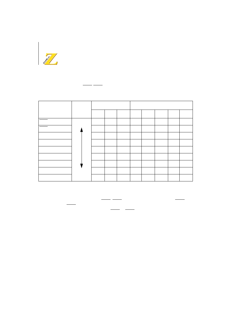
vector of INT1 INT2 and internal interrupt are summarized in Table 9.
Interrupt Acknowledge Cycle Timings
Figure 43 illustrates INT1, INT2, and internal interrupts timing. INT1 and
INT2 are sampled at the falling edge of the clock state prior to T2 or T1 in
the last machine cycle. If INT1 or INT2 is asserted Low at the falling
edge of clock state prior to T3 or T1 in the last machine cycle, the
interrupt request is accepted.
Table 9.
Vector Table
Interrupt Source
Priority
IL
Fixed Code
b7
b6
b5
b4
b3
b2
b1
b0
INT1
—
—
—
0
0
0
0
0
INT2
—
—
—
0
0
0
1
0
PRT channel 0
—
—
—
0
0
1
0
0
PRT channel 1
—
—
—
0
0
1
1
0
DMA channel 0
—
—
—
0
1
0
0
0
DMA channel 1
—
—
—
0
1
0
1
0
CSI/O
—
—
—
0
1
1
0
0
ASCI channel 0
—
—
—
0
1
1
1
0
ASCI channel 1
—
—
—
1
0
0
0
0
Highest
Lowest
