Prt interrupts, Prt and reset – Zilog Z80180 User Manual
Page 179
Z8018x
Family MPU User Manual
164
UM005003-0703
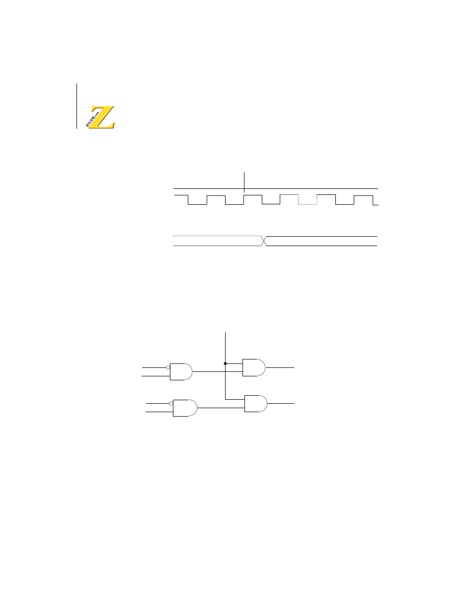
Figure 65. Timer Output Timing Diagram
PRT Interrupts
The PRT interrupt request circuit is illustrated in Figure 66.
Figure 66. PRT Interrupt Request Generation
PRT and RESET
During RESET, the bits in TCR are initialized as defined in the TCR
register description. Down counting is stopped and the TMDR and RLDR
registers are initialized to
FFFFH
. The A18/TOUT pin reverts to the
address output function.
TOUT
Phi
Timer Data
Reg. = 0001H
Timer Data
Reg. = 0000H
TIF1
TIE1
TIF0
TIE0
IEF1
PRT1 Interrupt
Request
PRT0 Interrupt
Request