Programmable reload timer (prt), Figure 62. csi/o receive timing–external clock, Prt block diagram – Zilog Z80180 User Manual
Page 171
Z8018x
Family MPU User Manual
156
UM005003-0703
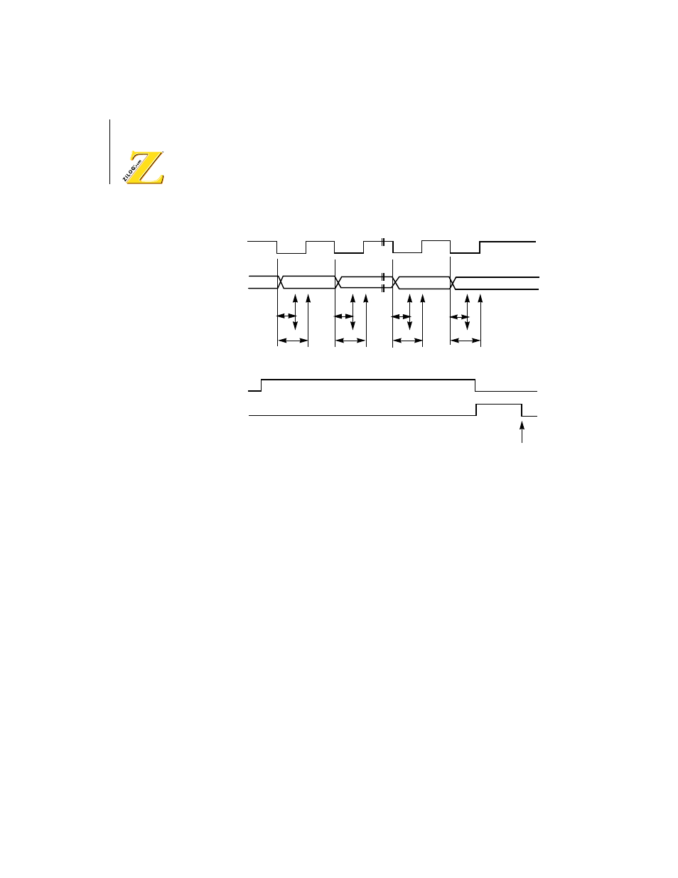
Figure 62. CSI/O Receive Timing–External Clock
Programmable Reload Timer (PRT)
The Z8X180 contains a two channel 16-bit Programmable Reload Timer.
Each PRT channel contains a 16-bit down counter and a 16-bit reload
register. The down counter is directly read and written and a down counter
overflow interrupt can be programmably enabled or disabled. Also, PRT
channel 1 features a TOUT output pin (multiplexed with A18) which can be
set High, Low, or toggled. Thus, PRT1 can perform programmable output
waveform generation.
PRT Block Diagram
The PRT block diagram is depicted in Figure 63. The two channels
feature separate timer data and reload registers and a common status/
CKS
RXS
RE
EF
Read or write of CSI/O
Transmit/Receive
Data Register
11.5
f
Sampling
LSB
MSB
11.5
f
11.5
f
11.5
f
16.5
f
16.5
f
16.5
f
16.5
f