Figure 38. int0 mode 1 timing, Int0 mode 2 – Zilog Z80180 User Manual
Page 93
Z8018x
Family MPU User Manual
78
UM005003-0703
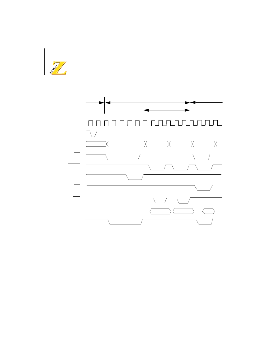
Figure 38. INT0 Mode 1 Timing
INT0 Mode 2
This method determines the restart address by reading the contents of a
table residing in memory. The vector table consists of up to 128 two-byte
restart addresses stored in low byte, high byte order.
Phi
A0
–
A19
WR
RD
MREQ
D0
–
D7
M1
PCH
PCL
PC
SP-1
SP-2
0038H
INT0
T1
T3
TW*
T2
T1
T2
T3
T1
T2
T3
T1
T2
T3
TW*
Last MC
PC is pushed onto stack
Op Code Fetch Cycle
INT0 Acknowledge Cycle
*Two Wait States are automatically inserted
ST
IORQ