Figure 70. external clock interface, Table 25, Z8x180 operating frequencies – Zilog Z80180 User Manual
Page 184
Z8018x
Family MPU User Manual
UM005003-0703
169
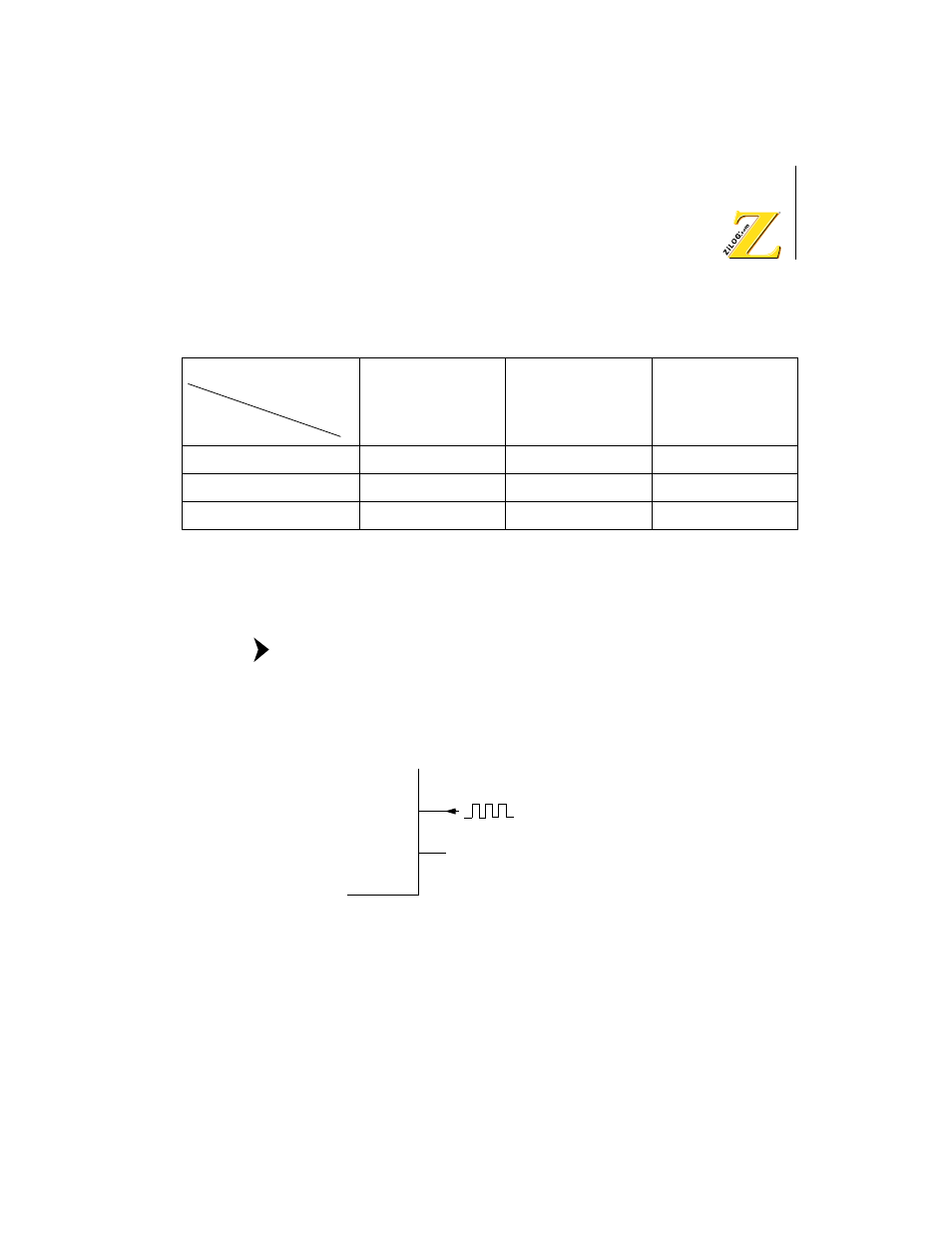
If an external clock input is used instead of a crystal, the waveform (twice
the clock rate) must exhibit a 50%
± 10% duty cycle.
The minimum clock input High voltage level is V
CC
–0.6V. The
external clock input is connected to the EXTAL pin, while the
XTAL pin is left open. Figure 70 depicts the external clock
interface.
Figure 70. External Clock Interface
Figure 71 illustrates the Z8X180 clock generator circuit while Figures 72
and 72 specify circuit board design rules.
Table 25. Z8X180 Operating Frequencies
4MHz
4MHz
<
f
£
12MHz 12MHz
<
f
£
33MHz
Co
<
7 pF
<
7 pF
<
7 pF
Rs
<
60
W
<
60
W
<
60
W
CL1, CL2
10 to 22 pF
±
10%
10 to 22 pF
±
10%
10 to 22 pF
±
10%
Clock
Item
Frequency
Note:
EXTAL
XTAL
3
2 Open
External Clock Input