Figure 7, Figure 8 – Zilog Z80180 User Manual
Page 32
Z8018x
Family MPU User Manual
UM005003-0703
17
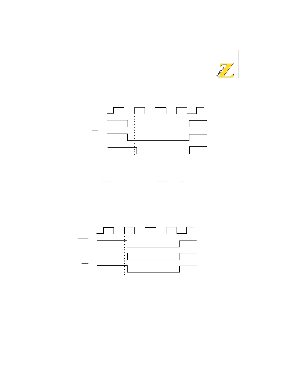
Figure 7.
I/O Read and Write Cycles with IOC = 1 Timing Diagram
When IOC is
0
, the timing of the IORQ and RD signals match the timing
required by the Z80 family of peripherals. The IORQ and RD signals go
active as a result of the rising edge of T2. This timing allows the Z8X180
to satisfy the setup times required by the Z80 peripherals on those two
signals (Figure ).
Figure 8.
I/O Read and Write cycles with IOC = 0 Timing Diagram
For the remainder of this document, assume that M1E is
0
and IOC is
0
.
T1
Phi
T2
TW
T3
IORQ
RD
WR
T1
Phi
T2
TW
T3
IORQ
RD
WR