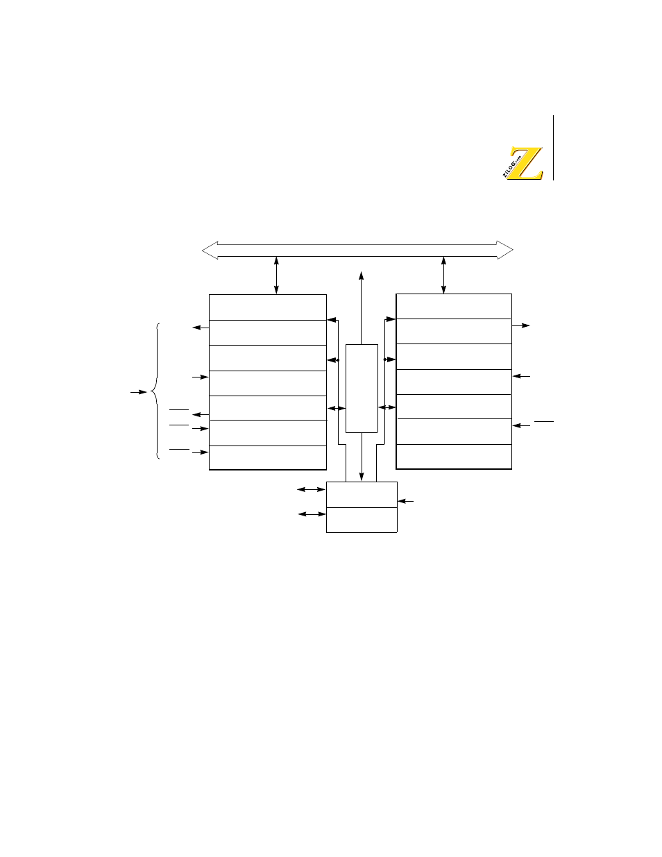
Figure 52. asci block diagram, Asci register description, Z8018x family mpu user manual – Zilog Z80180 User Manual
Page 132

Z8018x
Family MPU User Manual
UM005003-0703
117
Figure 52. ASCI Block Diagram
ASCI Register Description
The following subparagraphs explain the various functions of the ASCI
registers.
ASCI Transmit Shift Register 0, 1 (TSR0, 1)
When the ASCI Transmit Shift Register receives data from the ASCI
Transmit Data Register (TDR), the data is shifted out to the TXA pin.
TXA1
Phi
Internal Address/Data Bus
Interrupt Request
ASCI Transmit Data Register
ch 0 : TDR0
ASCI Transmit Shift Register*
ch 0 : TSR0
ASCI Receive Data Register
ch 0 : RDR0
ASCI Receive Shift Register*
ch 0 : RSR0 (8)
ASCI Control Register A
ch 0 : CNTLA0 (8)
ASCI Control Register B
ch 0 : CNTLB0 (8)
ASCI Status Register
ch 0 : STAT0 (8)
CKA1
* Not program Accessible
Baud Rate
Generator 0
Baud Rate
Generator 1
ASCI Status Register
ch 1 : STAT1 (8)
ASCI Control Register B
ch 1 : CNTLB1 (8)
ASCI Control Register A
ch 1 : CNTLA1 (8)
ASCI Transmit Data Register
ch 1 : TDR1
ASCI Transmit Shift Register*
ch 1 : TSR1
ASCI Receive Data Register
ch 1 : RDR1
ASCI Receive Shift Register*
ch 1 : RSR1 (8)
ASCI
Control
RXA1
CKA0
CTS1
RTS0
CTS0
DCD0
TXA0
RXA0
