Interrupt vector register (i), Interrupt vector low register – Zilog Z80180 User Manual
Page 81
Z8018x
Family MPU User Manual
66
UM005003-0703
Interrupt Vector Register (I)
Mode 2 for INT0 external interrupt, INT1 and INT2 external interrupts,
and all internal interrupts (except TRAP) use a programmable vectored
technique to determine the address at which interrupt processing starts. In
response to the interrupt a 16-bit address is generated. This address
accesses a vector table in memory to obtain the address at which
execution restarts.
While the method for generation of the least significant byte of the table
address differs, all vectored interrupts use the contents of I as the most
significant byte of the table address. By programming the contents of I,
vector tables can be relocated on 256 byte boundaries throughout the
64KB logical address space.
I is read/written with the LD A, I and LD I, A instructions rather
than I/O (IN, OUT) instructions. I is initialized to
00H
during
RESET.
Interrupt Vector Low Register
This register determines the most significant three bits of the low-order
byte of the interrupt vector table address for external interrupts INT1 and
INT2 and all internal interrupts (except TRAP). The five least significant
bits are fixed for each specific interrupt source. By programming IL, the
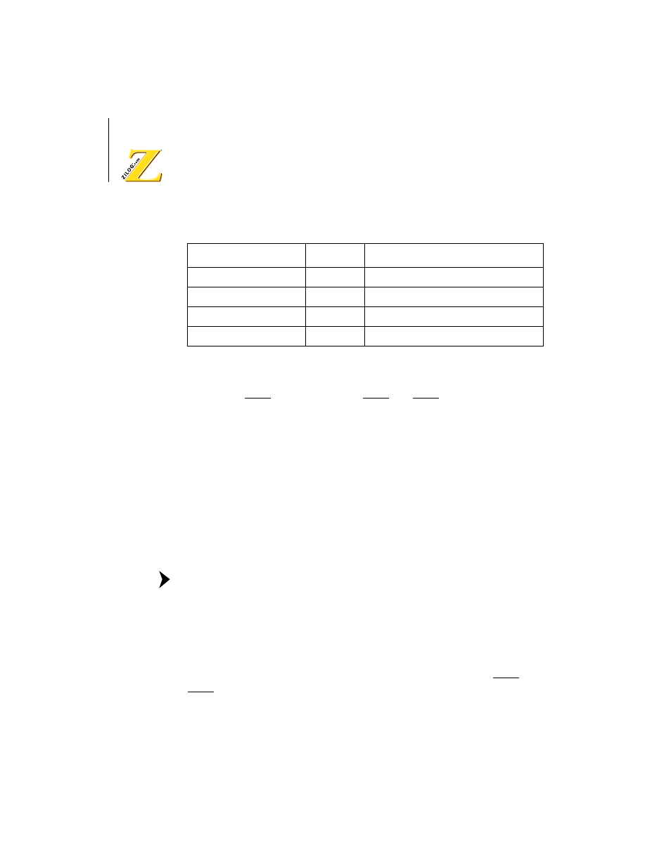
Function
Name
Access Method
Interrupt Vector High
I
LD A,I and LD I, A instructions
Interrupt Vector Low
IL
I/O instruction (addr = 33H)
Interrupt/Trap Control
ITC
I/O instruction (addr = 34H)
Interrupt Enable Flag 1,2 IEF1, IEF2 El and DI
Note: