Figure 41. int1, int2 vector acquisition – Zilog Z80180 User Manual
Page 96
Z8018x
Family MPU User Manual
UM005003-0703
81
also the interrupt response sequence used for all internal interrupts
(except TRAP).
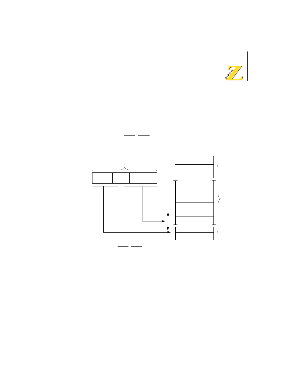
As depicted in Figure 41, the low-order byte of the vector table address
has the most significant three bits of the software programmable IL
register while the least significant five bits are a unique fixed value for
each interrupt (INT1, INT2 and internal) source:
Figure 41. INT1, INT2 Vector Acquisition
INT1 and INT2 are globally masked by IEF1 is
0
. Each is also
individually maskable by respectively clearing the ITE1 and ITE2 (bits
1,2) of the INT/TRAP control register to
0
.
During RESET, IEF1, ITE1 and ITE2 bits are reset to
0
.
Internal Interrupts
Internal interrupts (except TRAP) use the same vectored response mode
as INT1 and INT2. Internal interrupts are globally masked by IEF1 is
0
.
Individual internal interrupts are enabled/disabled by programming each
Vector + 1
Vector
32 Bytes
Vector
Table
16-bit Vector
High-order 8 bits
Low-order 8 bits
of starting address
of starting address
I
IL
Fixed Code
(5 bits)
Memory