Figure 44. refresh cycle timing diagram – Zilog Z80180 User Manual
Page 102
Z8018x
Family MPU User Manual
UM005003-0703
87
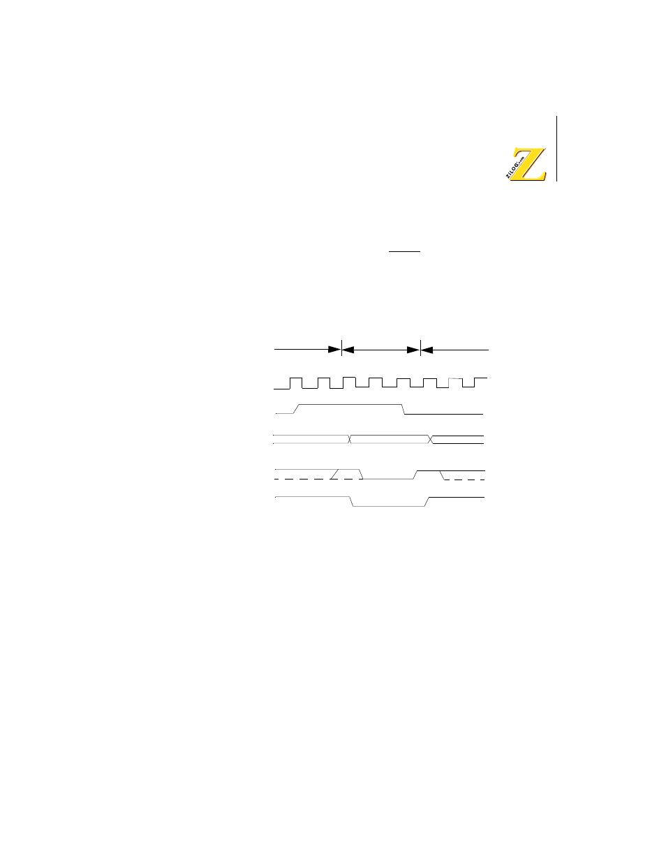
Refresh cycles may be programmed to be either two or three clock cycles
in duration by programming the REFW (Refresh Wait) bit in the Refresh
Control Register (RCR). The external WAIT input and the internal Wait
State generator are not effective during refresh.
Figure 44 depicts the timing of a refresh cycle with a refresh wait (TRW)
cycle.
Figure 44. Refresh Cycle Timing Diagram
NOTE: * If three refresh cycles are specified, TRW is inserted.
Otherwise, TRW is not inserted
MC: Machine Cycle
MCi Refresh
cycle
MCi+1
TR1
TRW* TR2
Refresh signal
(Internal signal)
Refresh address
A0 — A7
MREQ
RFSH