Figure 19. memory and i/o wait state insertion, Dcntl – dma/wait control register), Table 3 – Zilog Z80180 User Manual
Page 44: Memory wait states
Z8018x
Family MPU User Manual
UM005003-0703
29
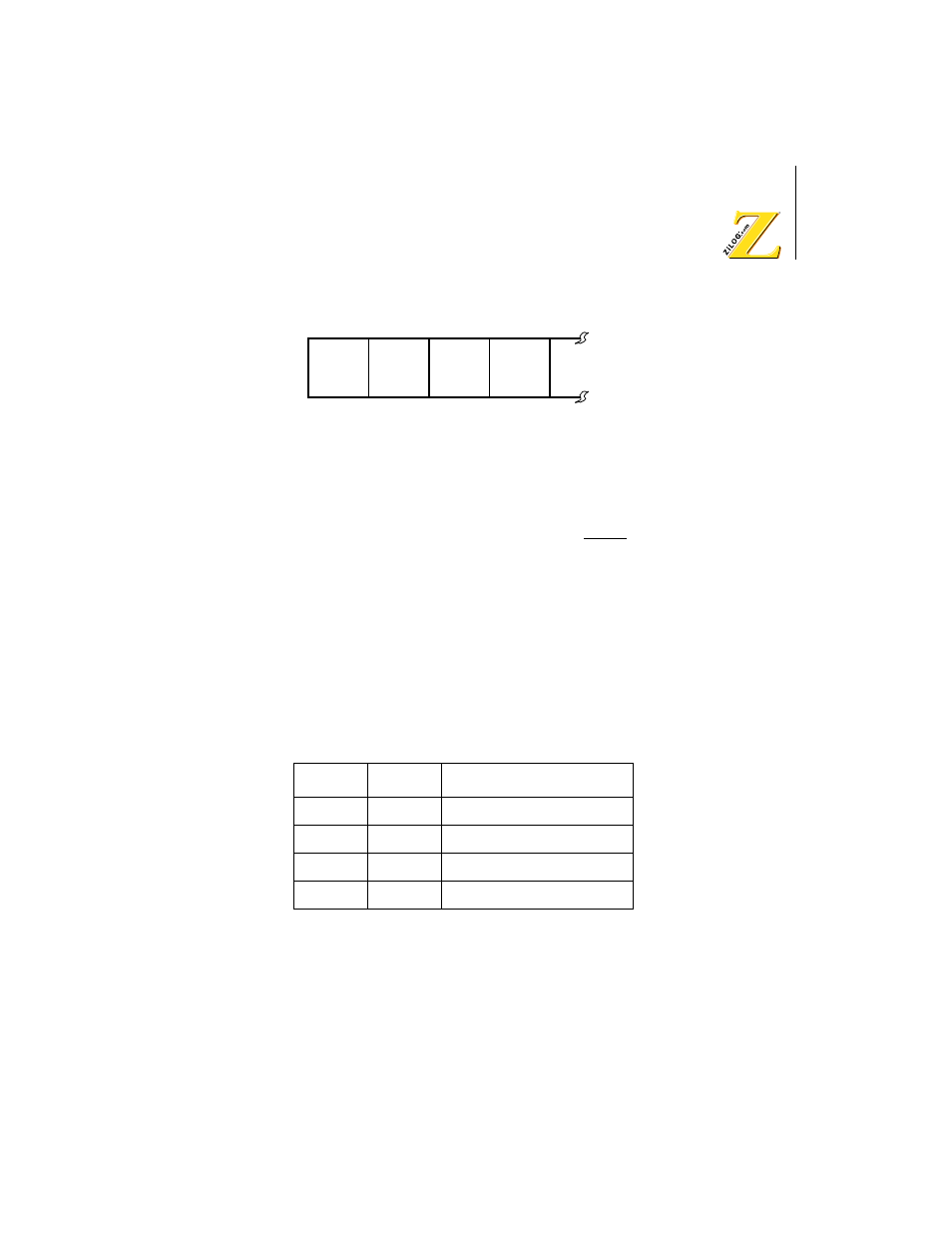
Figure 19. Memory and I/O Wait State Insertion (DCNTL – DMA/Wait
Control Register)
The number of Wait States (TW) inserted in a specific cycle is the
maximum of the number requested by the WAIT input, and the number
automatically generated by the on-chip Wait State generator.
Bit 7, 6: MWI1 MWI0, (Memory Wait Insertion)
For CPU and DMAC cycles which access memory (including memory
mapped I/O), zero to three Wait States may be automatically inserted
depending on the programmed value in MWI1 and MWI0 as depicted in
Table 3
Bit 5, 4: IWI1, IWI0 (I/O Wait Insertion)
For CPU and DMA cycles which access external I/O (and interrupt
acknowledge cycles), one to six Wait States (TW) may be automatically
Table 3.
Memory Wait States
MW11
MWI0
The Number of Wait States
0
0
0
0
1
1
1
0
2
1
1
3
Bit
7
6
5
4
MWI1
MWI0
MWI1
MWI0
R/W
R/W
R/W
R/W