Allied Telesis AT-S62 User Manual
Page 290
Chapter 17: Class of Service
Section II: Advanced Operations
290
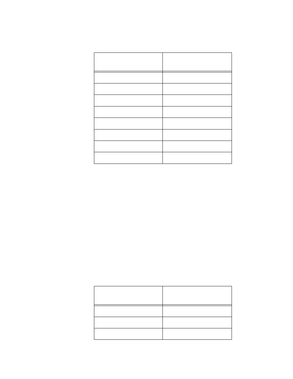
Table 7 lists the mappings between the eight CoS priority levels and the
four egress queues of a switch port.
For example, if a tagged packet with a priority level of 3 entered a port
on the switch, the switch would store the packet in Q1 queue on the
egress port.
Priority 0 is mapped to CoS queue 1 instead of CoS queue 0 because
tagged traffic that has never been prioritised has a VLAN tag User
Priority of 0. If priority 0 was mapped to CoS queue 0, this default traffic
goes to the lowest queue, which is probably undesirable. This mapping
also makes it possible to give some traffic a lower priority than the
default traffic.
You can change these mappings. For example, you might decide that
packets with a priority of 5 need to be handled by egress queue Q3 and
packets with a priority of 2 should be handled in Q1. The result is shown
in Table 8..
Table 7 Default Mappings of IEEE 802.1p Priority Levels to Priority Queues
IEEE 802.1p Priority
Level
Port Priority Queue
0
Q1
1
Q0
2
Q0
3
Q1
4
Q2
5
Q2
6
Q3
7
Q3
Table 8 Customized Mappings of IEEE 802.1p Priority Levels to Priority
Queues
IEEE 802.1p Priority
Level
Port Priority Queue
0
Q1
1
Q0
2
Q1