Allied Telesis AT-S62 User Manual
Page 222
Chapter 14: Classifiers
Section II: Advanced Operations
222
802.1p Priority Level (Layer 2)
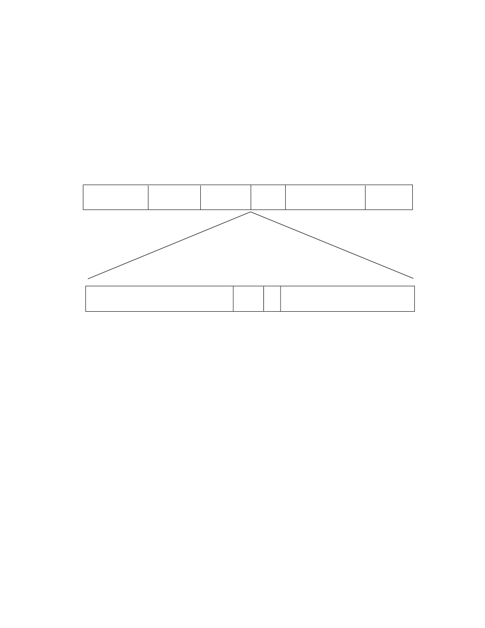
A tagged Ethernet frame, as explained in Tagged VLAN Overview on
page 523, contains within it a field that specifies its VLAN membership.
Such frames also contain a user priority level used by the switch to
determine the Quality of Service to apply to the frame and which egress
queue on the egress port a packet should be stored in. The three bit
binary number represents eight priority levels, 0 to 7, with 0 the lowest
priority and 7 the highest. Figure 65 illustrates the location of the user
priority field within an Ethernet frame.
Figure 65 User Priority and VLAN Fields within an Ethernet Frame
You can identify a traffic flow of tagged packets using the user priority
value. A classifier for such a traffic flow would instruct a port to watch for
tagged packets containing the specified user priority level.
The priority level criterion can contain only one value, and the value
must be from 0 (zero) to 7. Multiple classifiers are required if a port is to
watch for several different traffic flows of different priority levels.
VLAN ID (Layer 2)
A tagged Ethernet frame also contains within it a field of 12 bits that
specifies the ID number of the VLAN to which the frame belongs. The
field, illustrated in Figure 65, can be used to identify a traffic flow.
A classifier can contain only one VLAN ID. To create a port ACL or QoS
policy that applies to several different VLAN IDs, multiple classifiers are
required.
Preamble
Destination
Address
Source
Address
Type/
Length
Frame Data
CRC
64 bits
48 bits
48 bits
16
bits
368 to 12000 bits
32 bits
Tag Protocol Identifier
User
Priority CFI
VLAN Identifier
16 bits
3 bits
1
bit
12 bits