Settings relating to signal outputs, Setting the active area – Sony GP-X1EM Grip Extension User Manual
Page 456

456
Applying the video process effect
In the
For details about the video process, see “Applying the
video process effect” (page 192).
Applying the primary color correction
effect
In the
>Switcher >Input >Input FC/CCR >Input CCR menu
(7332.9), press [Primary CCR], turning it on.
For details about primary color correction settings, see
“Applying the primary color correction effect”
(page 193).
Applying the RGB clip effect
In the
>Switcher >Input >Input FC/CCR >Input CCR menu
(7332.9), press [RGB Clip], turning it on.
For details about RGB clip settings, see “Applying the
RGB clip effect” (page 193).
Setting the Active Area
You can set a 3840×2160 or 4096×2160 active area for
groups of four inputs when the signal format is
3840×2160P.
• On the XVS-9000, the active area cannot be set.
• [4096×2160] input signals can be selected only on AUX
bus outputs set to [4096Ч2160].
• [4096Ч2160] is supported on the XKS-S8110 SDI Input
Connector Board only.
1
In the Engineering Setup >Switcher >Input menu
(7332), press [Active Area Size].
The Active Area Size menu (7332.4) appears.
2
Select the target input to set.
3
In the
3840×2160:
Set to 3840Ч2160.
4096Ч2160:
Set to 4096×2160.
Settings Relating to
Signal Outputs
Configures settings for outputs and format converter
outputs.
The following output connector boards can be installed in
the XVS-9000/8000/7000/6000.
• XVS-9000
• XVS-8000/7000/6000
a) Interface configured in the Engineering Setup >System >Network Config
>Net I/F Protocol menu (7311.3)
The maximum number of outputs on the XVS-9000 is 80
(40 for 4K format), or 96 (48 for 4K format) when the
multi viewer output connectors are included.
For the XVS-8000/7000/6000, the maximum number of
outputs on the XVS-8000/7000 is 48 (12 for 4K format),
and on the XVS-6000 is 24 (6 for 4K format). The
maximum number of format converter outputs is 16 (4 for
4K format).
59.94 (2×) format output signals are supported on the
XKS-S8165 SDI Output Connector Board only.
Network connector board restrictions
Only the following interface and signal format outputs are
supported, depending on the board.
Notes
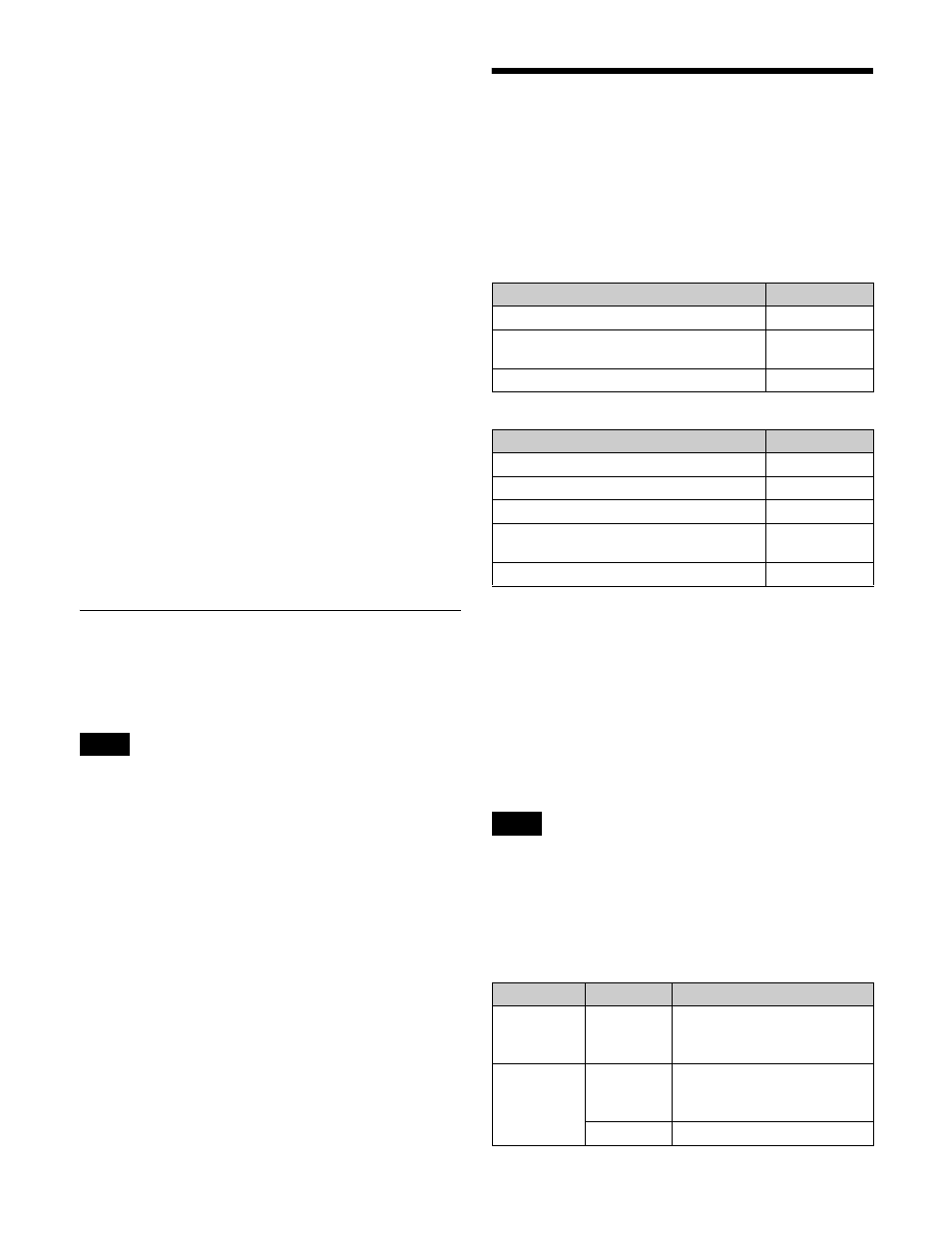
Output connector board
Interface
XKS-S9167 12G-SDI Output Board
SDI
XKS-C9121 100G IP Input and Output
Board
ST2110
XKS-C9121N NMI Input and Output Board NMI
Output connector board
Interface
XKS-S8165 SDI Output Connector Board
SDI
XKS-S8167 12G-SDI Output Board
SDI
XKS-T8165 IP Output Connector Board
NMI
XKS-Q8166 QSFP IP Output Connector
Board
NMI/ST2110
a)
XKS-C8166 100G IP Output Board
ST2110
Note
Board
Interface
Signal formats
XKS-T8165
NMI
• 3840×2160P 2SI (Level A)
a)
• 1080P (Level A)
b)
• 1080i
XKS-Q8166
NMI
• 3840×2160P 2SI (Level A)
a)
• 1080P (Level A)
b)
• 1080i
ST2110
• 1080i
c)
