Basic dme wipe setting operations, Selecting a dme wipe pattern – Sony GP-X1EM Grip Extension User Manual
Page 161

161
Basic DME Wipe Setting
Operations
You carry out DME wipe setting operations using the
DME Wipe menu for each bank.
This section describes operations on the M/E-1 bank
(M/E-1 >DME Wipe menu) as an example.
For details about independent key transition DME wipe
settings, see “Basic Independent Key Transition DME
Wipe Setting Operations” (page 166).
You can display the input image filling the frame when
executing a DME wipe by disabling the edge softness
function in the Setup menu.
For details, see “Setting the DME Wipe Edge Softness
Function” (page 469).
Selecting a DME Wipe Pattern
1
Display the DME wipe setting menu.
In 1-channel mode, open the M/E-1 >DME Wipe >1ch
menu (1161).
In 2-channel mode, open the M/E-1 >DME Wipe >2ch
menu (1162).
In 3-channel mode, open the M/E-1 >DME Wipe >3ch
menu (1163).
2
Press the button for the desired DME wipe pattern
group to select it.
The patterns from the selected pattern group appear on
the screen.
If executing a DME wipe using a resizer
Select [Resizer Slide], [Resizer Squeeze], or [Resizer
Frame I/O] in the DME wipe pattern group.
Resizer DME wipes can be used only when the next
transition event is a key.
3
Press the desired pattern to select it.
Adjusting DME wipe pattern parameters
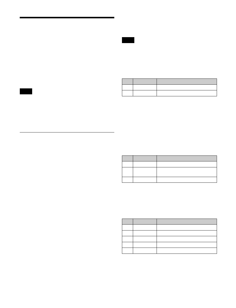
Of the DME wipe patterns, the following have parameters
that can be adjusted.
In an independent key transition, DME wipe pattern
parameters cannot be configured.
When Squeeze (for one channel) is selected
(pattern numbers 1032, 1033)
When Crop Slide (for two channels) is selected
(pattern numbers 2661, 2662)
a) Set relative to a transition start point of 0% and end point of 100%.
When Page Turn (for one channel) is selected
(pattern numbers 1301 to 1313, 1315 to 1318, 1341
to 1345)
When Page Turn (for two channels) is selected
(pattern numbers 2701 to 2713, 2715 to 2718, 2741
to 2745)
When Roll (for one channel) is selected (pattern
numbers 1321 to 1333, 1335 to 1338, 1346 to 1350)
When Roll (for two channels) is selected (pattern
numbers 2721 to 2733, 2735 to 2738, 2746 to 2750)
a) 0% is an effect like a turned page, 100% is normal curl, and 200% is radius
with double the normal curl.
b) The angle of rotation range varies depending on the pattern.
–100.00 is rotation in the counterclockwise direction, +100.00 is rotation
in the clockwise direction, and 0.00 is no rotation.
When Brick (for two channels) is selected
(pattern numbers 2801 to 2804, 2811 to 2814)
a) The horizontal center position of the video pasted on Side V. At –100.00,
the center is at the left edge of the screen. At +100.00, the center is at the
right edge of the screen.
b) The vertical center position of the video pasted on Side V. At –100.00, the
center is at the bottom edge of the screen. At +100.00, the center is at the
top edge of the screen.
Note
Note
No.
Parameter
Adjustment
1
Holding Level Position for entering the dead band
a)
2
Tolerance
Width of the dead band
No.
Parameter
Adjustment
1
Radius
Radius of the turned page flap
a)
2
Magnitude
Angle of rotation through course of
transition
b)
3
Start Angle
Angle at start of transition
b)
No.
Parameter
Adjustment
1
Side V Size X Horizontal scaling factor
2
Side V Size Y Vertical scaling factor
3
Height
Height of brick
4
Center X
Horizontal center position
a)
5
Center Y
Vertical center position
b)
