2094 iam/am module connector data – Rockwell Automation 2094-xMxx-S Kinetix 6000 Multi-axis Servo Drives User Manual User Manual
Page 58
58
Rockwell Automation Publication 2094-UM001H-EN-P - June 2013
Chapter 4
Connector Data and Feature Descriptions
2094 IAM/AM Module
Connector Data
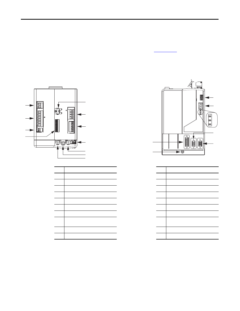
Use these illustrations to identify the connectors and indicators for the IAM/AM
modules. Sercos interface and Ethernet network connectors for the
Kinetix 6000M IPIM module are also shown. For the remainder of the IPIM
module features and indicators, refer to the Kinetix 6000M Integrated Drive-
Motor System User Manual, publication
.
Although the physical size of the 400V-class module is larger than the 200V-class
module,
the location of the features and indicators is identical.
Figure 23 - Integrated Axis Module Features and Indicators
Item
Description
Item
Description
1
Safe torque-off (STO) connector
11
Sercos receive (Rx) connector
2
Contactor enable (CED) connector
12
Mounting screw
3
DC bus/AC input power (IPD) connector
13
I/O (IOD) connector
4
Control power (CPD) connector
14
Sercos node address switch
5
Motor cable shield clamp
15
Seven-segment fault status indicator
6
Motor power (MP) connector
16
Drive status indicator
7
Motor/resistive brake (BC) connector
17
COMM status indicator
8
Sercos communication rate and
optical power switches
18
Bus status indicator
9
Sercos transmit (Tx) connector
19
Motor feedback (MF) connector
10
DPI connector
20
Auxiliary feedback (AF) connector
BAUD
RATE
TX
RX
DPI
DC-
DC+
L3
L2
L1
CONT EN-
CONT EN+
W
V
U
MBRK -
MBRK +
COM
PWR
DBRK -
DBRK +
CTRL 2
CTRL 1
1 2 3 4
1 2 3 4 5 6
1 2
1 2 3 4 5 6
1 2
1 2 3 4 5 6 7 8 9
9
10
11
19
14
15
16
17
18
12
13
20
6
7
8
2
3
4
1
5
Kinetix 6000 IAM Module, Top View
(2094-AC05-M01-S module is shown)
Kinetix 6000 IAM Module, Front View
(2094-AC05-M01-S module is shown)