Rockwell Automation 2094-xMxx-S Kinetix 6000 Multi-axis Servo Drives User Manual User Manual
Page 243
Rockwell Automation Publication 2094-UM001H-EN-P - June 2013
243
Configure the Load Observer Feature
Appendix D
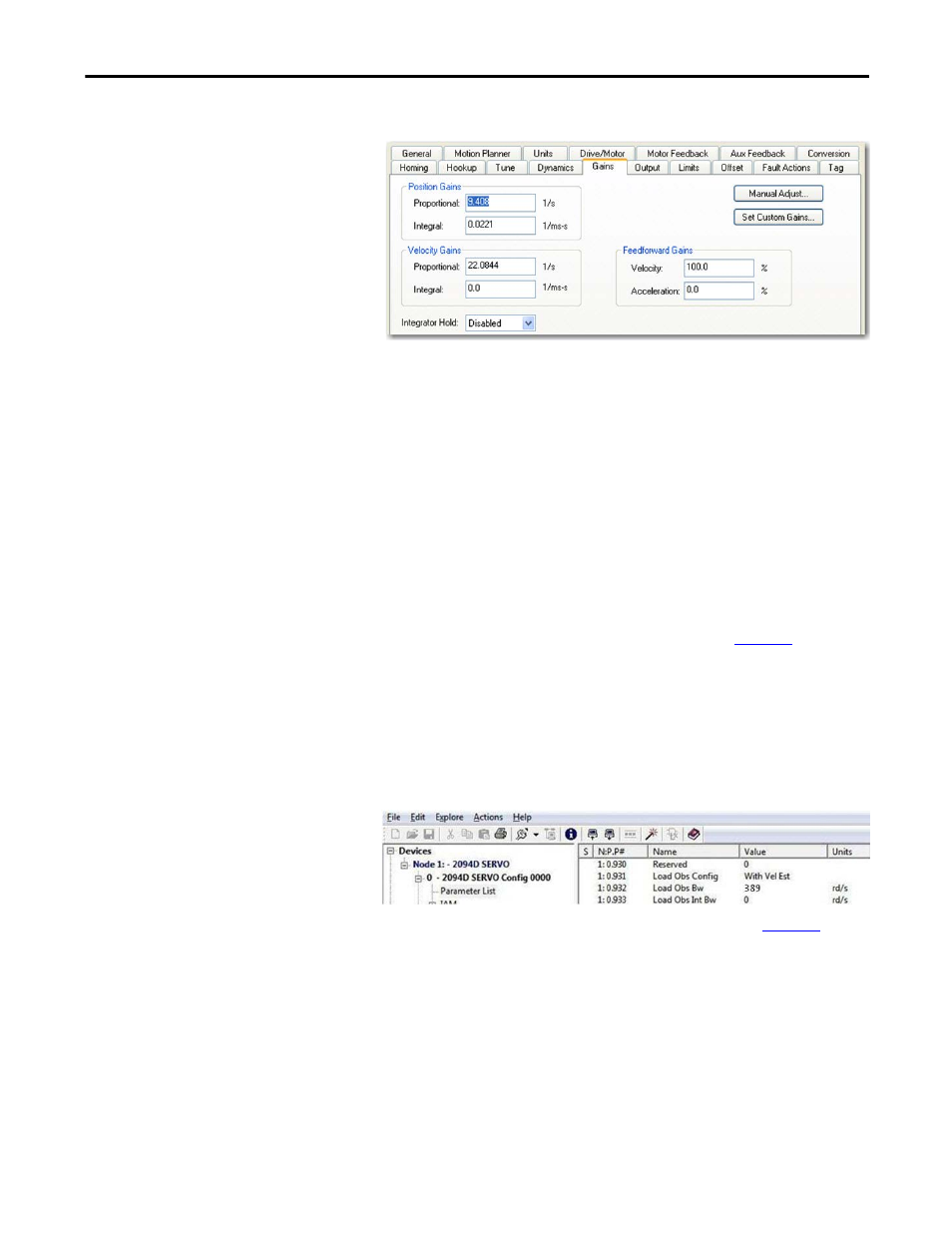
2. Configure these settings and values on the Gains tab.
a. Set the Position Proportional Gain = Kpp
b. Position Integral gain = Kpi
c. Velocity Proportional Gain = Kvp
d. Velocity Integral Gain = Kvi
3. If the Low-pass Output Filter is enabled, verify that the Low-pass Output
Filter Bandwidth
≥ Velocity Proportional Gain x 5/(2pi).
The compliant setting reduces all of the gains by a factor of the Load
Inertia Ratio +1 and then calculates the Load Observer Bandwidth.
Typically, this reduction is too conservative, making the loop response too
sluggish and the error too large, however, it does provide stability.
To manually increase the gains by some factor to optimize the response,
refer to Manual Tuning for Further Optimization on
4. Configure these IDN parameter values.
a. IDN P-431 = 2 (Load Observer with Velocity Estimate)
b. IDN P-432 = Kop
c. IDN P-433 = 0
d. IDN P-065 = 1
5. Refer to Compensate for High Frequency Resonances on
, to
tune-out resonant frequencies.