Rockwell Automation 2094-xMxx-S Kinetix 6000 Multi-axis Servo Drives User Manual User Manual
Page 268
268
Rockwell Automation Publication 2094-UM001H-EN-P - June 2013
Appendix G
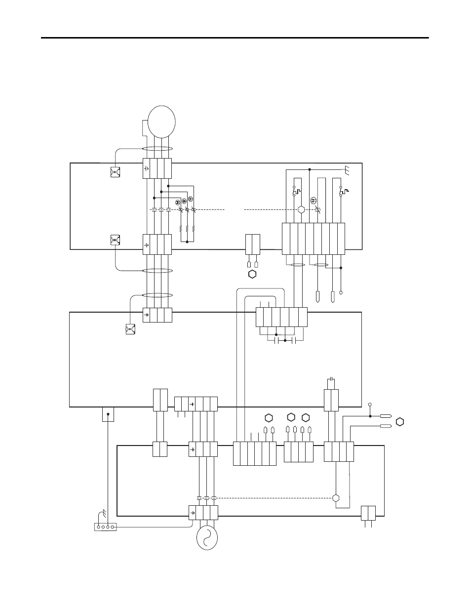
RBM Module Interconnect Diagrams
This example diagram shows 2094-
xCxx-Mxx and 2094-xMxx drives (without
safe torque-off ) and 2094-AL
xxS, 2094-BLxxS, and 2094-XL75S LIM modules
wired with the Bulletin 2090 RBM module.
Figure 122 - RBM Wiring Example, Category 2 Configuration per ISO 13849-1
T2
T1
K
4
3
2
1
4
3
2
1
D
C
B
A
IO_PWR1
BRKTMP0
CONT EN-
CONT EN+
W
V
U
L3
L2
L1
2, 4, 6
8
1, 3, 5
7
DC-
DC+
L3
L2
L1
CTRL 2
CTRL 1
L3'
L2'
L1'
1
2
1
2
3
4
5
6
1
2
6
5
4
3
2
1
4
3
2
1
W_DRIVE
V_DRIVE
U_DRIVE
W_M
TR
V_M
TR
U_M
TR
SHIELD
COIL_A2
COIL_A1
SHIELD
CONST
AT_42
CONST
AT_41
TS_22
TS_21
MBRK -
MBRK +
CO
M
PWR
DBRK -
DBRK +
8
7
6
5
4
3
2
1
K
IO_C
OM1
COIL_E2
IO_PWR1
COIL_E1
BRKST
AT0
IO_PWR1
L1
L2
L3
AUX3
AUX2
AUX1
R3
R2
R1
W
V
U
GND
M
AUX4
1
2
3
4
5
6
D
1
2
2
1
L2
L1
IO_PWR2
IO_C
OM2
IO_PWR2
IO_C
OM2
IO_PWR2
IO_C
OM2
1
2
3
4
AUX1_L1
AUX1_L2
AUX2_L1
AUX2_L2
B
B
A
CTRL 2
CTRL 1
1
2
3
4
C
L1
L2/N
1
2
1
2
3
4
Not
e 1
Not
e 4
Not
e 1
Au
xi
liar
y 230V A
C
Inp
ut (
TB
4) C
onn
ec
tor
(2
090-
XB
120
-xx
on
ly)
Kinetix 600
0
In
tegra
ted A
xis Mo
dule
2094-
AC
xx
-M
xx
or 2
094-BC
xx
-M
xx
(A
xi
s_
0)
Ca
bl
e S
hi
el
d
Cl
amp
2090-
XX
NR
B-
14F0P7
RB
M
to
D
riv
e I
nter
face
C
able
Not
e 2
Mot
or C
onne
ct
ions
(T
B2) C
onnec
tor
Dri
ve
C
onne
ct
io
ns
(T
B1) C
onnec
tor
I/
O C
onnec
tions
(T
B3) C
onnec
tor
Refer
to
the
wirin
g exa
m
pl
es in
or mot
or
po
w
er
ca
ble
catalo
g
numb
ers
.
Not
e 2
Mo
to
r/
Resi
sti
ve
Br
ak
e (B
C)
C
on
nec
tor
Mot
or P
ow
er
(M
P) C
on
nec
tor
Cabl
e Shi
eld
Cl
am
p
Ca
bl
e S
hi
el
d
Cla
m
p
Mo
tor
P
ow
er
Co
nnec
tions
Bul
letin
2090
R
esi
st
iv
e Brak
e M
odu
le
2090
-XB
xx
-xx
(RBM_0)
Co
nt
ac
tor E
nab
le
(C
ED
) C
onne
ct
or
No
te
1
No
te
3
Co
nt
ro
l P
owe
r
(C
PD
) C
on
ne
ct
or
Po
w
er
R
ai
l
Gr
ou
nd
Stu
d
DC
B
us
and
Th
re
e-
ph
as
e
Inpu
t (IP
D)
Co
nnec
tor
24V DC
O
ut
put
(P
1L)
C
onne
ct
or
Th
re
e-
ph
as
e I
np
ut
(I
PL
) C
on
ne
ct
or
I/
O (
IOL)
Co
nne
ct
or
230V A
C O
utput
(P
2L) C
on
ne
ct
or
Th
re
e-
ph
as
e O
ut
pu
t
(O
PL)
C
onnec
tor
Sin
gle
-P
hase O
ut
put
(C
PL)
C
onne
ct
or
Bo
nde
d C
ab
ine
t
Gr
ou
nd Bu
s*
* Indic
at
es
U
ser
Su
pp
lied
Co
mponent
Bullet
in 2094
Line
Int
er
face Modu
le
2094-
A
Lxx
S, 2
094-BL
xx
S,
or 20
94-
XL75S
-C
2
230V A
C A
ux
ili
ar
y
Inp
ut P
ower
(A
PL)
C
onne
ct
or