Rockwell Automation 2094-xMxx-S Kinetix 6000 Multi-axis Servo Drives User Manual User Manual
Page 137
Rockwell Automation Publication 2094-UM001H-EN-P - June 2013
137
Configure and Start the Kinetix 6000 Drive System
Chapter 6
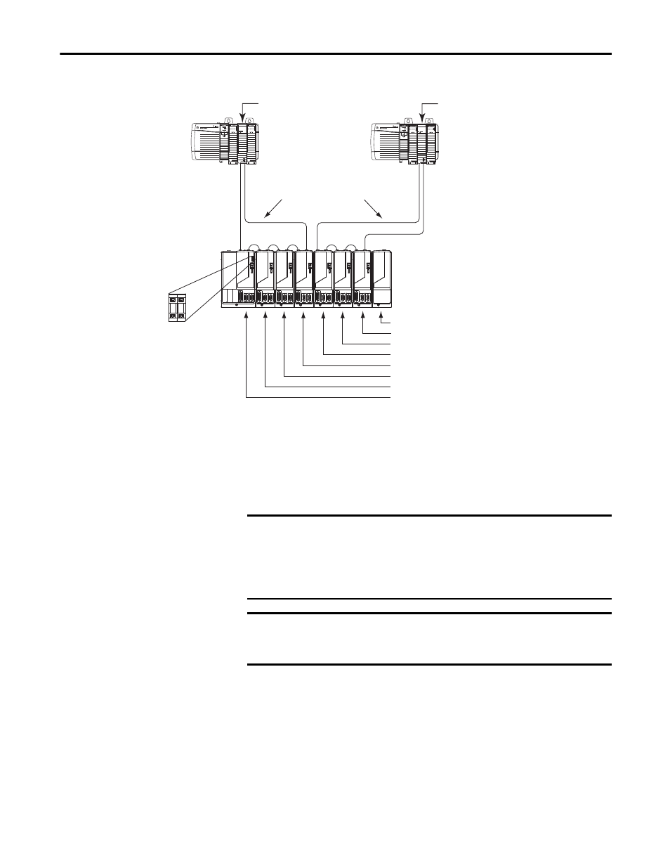
Figure 81 - Node Addressing Example 2
In this example, sercos interface module 1 controls axes
1…4 and module 2 controls axes 5…7. The slot-filler module is not assigned a
sercos node address, but the system identifies it with a slot location.
You can mount the two sercos interface modules in two separate ControlLogix
chassis (as shown) or you can mount them in the same chassis.
SERCOS interfaceTM
Tx (rear)
Rx (front)
OK
CP
SERCOS interfaceTM
Tx (rear)
Rx (front)
OK
CP
0 1
08 = Slot-filler module slot location
07 = AM module (axis 7) node address
06 = AM module (axis 6) node address
05 = AM module (axis 5) node address
04 = AM module (axis 4) node address
03 = AM module (axis 3) node address
02 = AM module (axis 2) node address
01 = IAM module (axis 1) base node address
Logix5000 Controller
(ControlLogix controller is shown)
Sercos Fiber-Optic rings
1756-MxxSE Sercos
interface Module 1
Kinetix 6000 Drive System
(8-axis power rail)
Receive
Receive
Transmit
Transmit
Transmit
Receive
Logix5000 Controller
(ControlLogix controller is shown)
1756-MxxSE Sercos
interface Module 2
Transmit
Receive
Base Node Address
Switches
IMPORTANT
The node address for each axis module is determined by the base node-address
switch setting on the IAM module.
Do not position axis modules to the right of shunt or slot-filler modules. The
added distance between non-adjacent axes can increase electrical noise and
impedance, and requires longer fiber-optic cable lengths.
IMPORTANT
Slot-filler modules must be used to fill any unoccupied slot on the power rail.
However, you can replace slot-filler modules with AM modules or the 2094-
BSP2 shunt module (maximum one 2094-BSP2 shunt module per power rail).