Rockwell Automation 2094-xMxx-S Kinetix 6000 Multi-axis Servo Drives User Manual User Manual
Page 202
202
Rockwell Automation Publication 2094-UM001H-EN-P - June 2013
Appendix A
Interconnect Diagrams
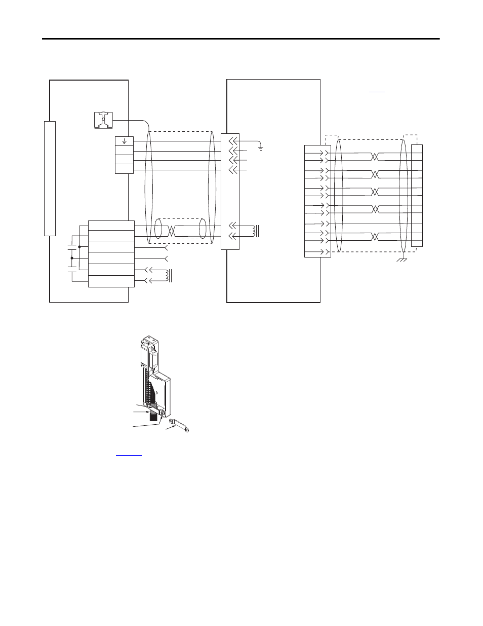
Figure 103 - AM Module (230V) Wiring Example with TL-Series Motors
(Bulletin TLY-A)
5
3
2
1
BR+
BR-
7
9
W
V
U
GND
1
2
3
4
5
6
7
8
9
10
11
12
13
14
15
4
3
2
1
6
5
4
3
2
1
Green/Yellow
Blue
Black
Brown
Black
White
W
V
U
MBRK -
MBRK +
COM
PWR
DBRK -
DBRK +
BR+
BR-
AM+
AM-
BM+
BM-
IM+
IM-
+5VDC
ECOM
WHT/BLUE
GREEN
WHT/GREEN
GRAY
WHT/GRAY
BLACK
WHT/BLACK
RED
WHT/RED
1
2
3
4
5
10
14
6
12
S1
S2
S3
YELLOW
WHT/YELLOW
13
8
SHIELD
22
23
15
24
17
19
9
10
11
12
13
14
Motor Brake
Three-phase
Motor Power
Motor Feedback
TLY-Axxxx-H (230V)
Servo Motors with
Incremental Feedback
2090-CFBM6DF-CBAAxx (flying-lead) or 2090-
CFBM6DD-CCAAxx (with drive-end connector)
Feedback Cable
Notes 16, 17
Resistive Brake
Connections
Motor/Resistive
Brake (BC) Connector
Motor Power
(MP) Connector
Cable Shield
Clamp
Note 10
IAM (inverter) or AM
Module
Note 15
2090-CPBM6DF-16AAxx
Motor Power and Brake Cable
Notes 16, 18
Use 2090-CPWM6DF-16AAxx
cable for continuous-flex
non-brake applications.
User Supplied
24V DC
Refer to low-profile connector
illustration (lower left)
for proper grounding technique.
Grounding Technique for
Feedback Cable Shield
Turn clamp over to hold
small cables secure.
Exposed shield secured
under clamp.
Clamp Screws (2)
Clamp
Refer to table on
page 186
for note information.
Motor Feedback
(MF) Connector
2090-K6CK-D15M
Connector Kit
2090-K6CK-D15M
Low-profile Connector Kit
Refer to Low Profile Connector Kit Installation Instructions,
publication
onnector kit specifications.