Dc common bus wiring examples – Rockwell Automation 2094-xMxx-S Kinetix 6000 Multi-axis Servo Drives User Manual User Manual
Page 191
Rockwell Automation Publication 2094-UM001H-EN-P - June 2013
191
Interconnect Diagrams
Appendix A
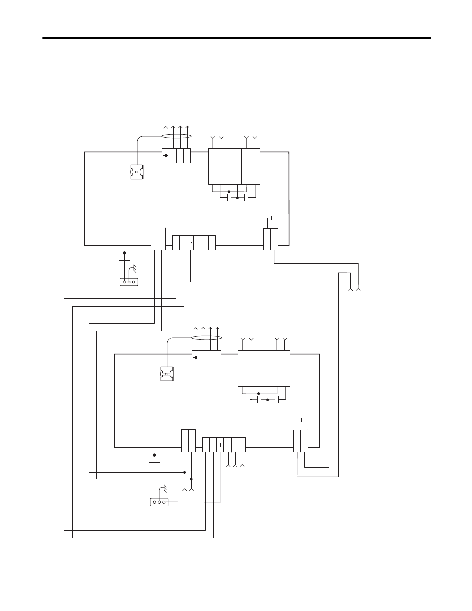
DC Common Bus Wiring Examples
Figure 91 - Leader IAM Module with Single Follower IAM Module
CONT EN-
CONT EN+
W
V
U
DC-
DC+
L3
L2
L1
CTRL 2
CTRL 1
1
2
1
2
3
4
5
6
1
2
6
5
4
3
2
1
4
3
2
1
CONT EN-
CONT EN+
W
V
U
DC-
DC+
L3
L2
L1
CTRL 2
CTRL 1
1
2
1
2
3
4
5
6
1
2
6
5
4
3
2
1
4
3
2
1
MBRK -
MBRK +
COM
PWR
DBRK -
DBRK +
N.C.
N.C.
N.C.
MBRK -
MBRK +
COM
PWR
DBRK -
DBRK +
Sin
gle
-p
hase I
npu
t
95
…
264
V A
C
RM
S
Not
es 1,
2
Th
re
e-
ph
as
e I
np
ut
fr
om
L
IM
or
Input P
ow
er C
ont
ac
to
r (M
1)
195…264V A
C RMS
or 324…528V A
C RMS
Not
es
1,
2, 7, 8
Co
nt
ro
l P
ow
er
(C
PD
) C
on
ne
ct
or
Po
w
er
R
ai
l
Gr
ou
nd St
ud
DC
Bus
and
Th
re
e-
ph
as
e
Inp
ut (I
PD)
Co
nnec
tor
Co
nt
ac
tor E
nab
le
(C
ED
) C
onne
ct
or
Mo
to
r/Resi
sti
ve
Br
ak
e (BC
) C
on
nec
tor
Th
re
e-
ph
as
e
Mot
or P
ow
er
Co
nn
ec
tio
ns
Not
e 16
Ca
bl
e S
hi
el
d
Cla
m
p
Not
e 10
Bo
nde
d Cabi
net
Gr
ou
nd
B
us
*
Co
nt
ro
l Po
w
er
(C
PD
) C
onnec
tor
Po
w
er
R
ai
l
Gr
ou
nd
S
tu
d
DC Bus
an
d
Th
re
e-
ph
as
e
In
put (
IP
D)
Co
nn
ec
to
r
Co
nt
ac
to
r Enab
le
(C
ED
) C
onnec
tor
Not
e 14
M
otor
/Re
si
st
iv
e
Brak
e (
BC
) C
onne
ct
or
Th
re
e-
ph
as
e
Mo
tor
P
ow
er
Co
nnec
tions
No
te
1
6
Cabl
e Shi
eld
Cl
am
p
Not
e 1
0
Bo
nd
ed C
ab
ine
t
Gr
ou
nd Bu
s*
Mot
or P
ow
er
(MP) C
onnec
tor
Mo
to
r P
ow
er
(M
P)
C
onne
ct
or
* In
dic
ates User
Su
pp
lied
C
omp
on
en
t
2094
-A
Cxx
-M
xx
-x
or
209
4-BC
xx
-M
xx
-x
Co
mmon-bu
s F
ollo
w
er
IA
M Mo
dule
2094-
AC
xx
-M
xx
-x
or
2094-BC
xx
-M
xx
-x
Common-bus L
eader
IA
M Mo
dule
W
ire
the l
ead
er a
nd
fol
low
er
IAM
co
nt
ac
to
r enable
te
rminals in series
w
ith the saf
et
y con
tr
ol str
ing o
r LIM I/O
.
Re
fe
r to
ta
ble
o
fo
r no
te
in
for
m
at
io
n.