Rockwell Automation 2094-xMxx-S Kinetix 6000 Multi-axis Servo Drives User Manual User Manual
Page 272
272
Rockwell Automation Publication 2094-UM001H-EN-P - June 2013
Appendix G
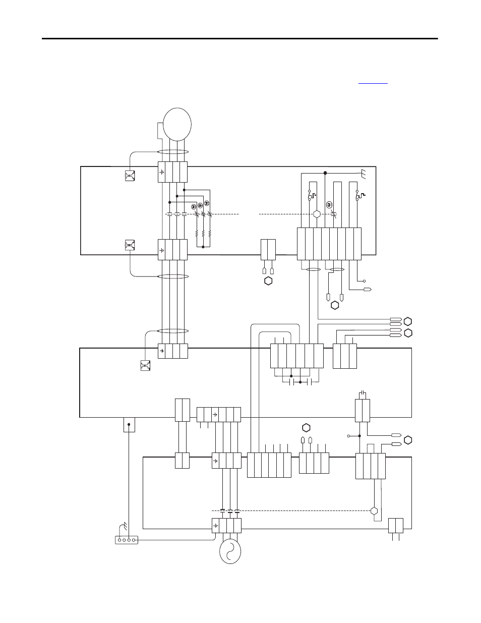
RBM Module Interconnect Diagrams
This example diagram shows 2094-
xCxx-Mxx drives (without safe torque-off )
and 2094-AL
xxS, 2094-BLxxS, and 2094-XL75S LIM modules wired with the
Bulletin 2090 RBM module. The example continues on
page 273
.
Figure 124 - RBM Wiring Example, Category 3 Configuration per ISO 13849-1
T2
T1
K
4
3
2
1
4
3
2
1
D
C
B
A
IO_PWR1
BRKTMP0
CONT EN-
CONT EN+
W
V
U
L3
L2
L1
DC-
DC+
L3
L2
L1
CTRL 1
CTRL 2
L3'
L2'
L1'
1
2
1
2
3
4
5
6
1
2
6
5
4
3
2
1
4
3
2
1
W_DRIVE
V_DRIVE
U_DRIVE
W_M
TR
V_M
TR
U_M
TR
SHIELD
COIL_A2
COIL_A1
SHIELD
CONST
AT_42
CONST
AT_41
TS_22
TS_21
MBRK -
MBRK +
CO
M
PWR
DBRK -
DBRK +
8
7
6
5
4
3
2
1
K
BRKST
AT0
IO_PWR1
L1
L2
L3
AUX3
AUX2
AUX1
R3
R2
R1
W
V
U
GND
M
AUX4
1
2
3
+24V_PWR
ENABLE
+24V_C
OM
B
C
D
E
2
1
L2
L1
1, 3, 5
2, 4, 6
7
8
1
2
3
4
5
6
1
2
IO_PWR2
IO_C
OM2
IO_PWR2
IO_C
OM2
IO_PWR2
IO_C
OM2
1
2
3
4
AUX1_L1
AUX1_L2
AUX2_L1
AUX2_L2
A
CTRL 2
CTRL 1
A
L1
L2/N
1
2
1
2
3
4
1
2
3
4
IO_PWR1
IO_C
OM1
COIL_E1
COIL_E2
Not
e 1
Not
e 4
Not
e 1
Au
xi
liar
y 2
30V
AC
Inpu
t (
TB4)
C
onnec
tor
(2090-
XB
120-
xx
onl
y)
K
ine
tix 6000
Int
egra
te
d Axis Module
209
4-A
Cxx
-M
xx
or
209
4-BC
xx
-M
xx
(A
xi
s_
0)
Cabl
e Sh
ield
Cl
amp
20
90-
XX
NRB
-1
4F0P7
RB
M t
o
D
riv
e In
ter
face
Cabl
e
Not
e 2
Mot
or
C
onnec
tions
(T
B2)
C
onne
ct
or
D
riv
e C
onnec
tions
(T
B1
) C
on
ne
ct
or
I/O C
on
nec
tio
ns
(T
B3
) C
on
ne
ct
or
Mot
or/R
esis
tiv
e
Br
ak
e (B
C)
C
onnec
tor
Mo
to
r P
ow
er
(M
P)
C
onne
ct
or
Ca
bl
e S
hi
el
d
Cla
m
p
Ca
bl
e S
hi
el
d
Clam
p
Mo
tor
P
ow
er
Co
nnec
tions
Bu
llet
in
209
0
Resi
st
iv
e Bra
ke
M
odu
le
209
0-
XB
xx
-xx
(RBM_0)
Co
nt
ac
to
r E
nab
le
(C
ED
) Co
nn
ec
to
r
Not
e 1
Not
e 3
Co
nt
ro
l Po
w
er
(C
PD
) C
onnec
tor
Po
w
er
R
ai
l
Gr
ou
nd S
tud
DC
Bus
and
Th
re
e-
ph
as
e
Inp
ut (
IPD)
Co
nnec
tor
Th
re
e-
ph
as
e I
np
ut
(I
PL)
C
onnec
tor
I/O (
IOL
)
Co
nn
ec
to
r
Th
re
e-
ph
as
e O
ut
pu
t
(O
PL)
C
onnec
tor
Si
ng
le
-P
ha
se
Ou
tp
ut
(C
PL)
C
onne
ct
or
Bo
nd
ed
C
abi
net
Gr
ou
nd
Bus
*
* In
dica
te
s U
ser
Supplied
C
om
pon
en
t
Bulletin
2094
Lin
e
In
ter
face
Mo
dule
209
4-A
Lxx
S,
20
94-B
Lxx
S,
or
2094-
XL75S-
C2
I/
O (
IOD
)
Co
nne
ct
or
Not
e 6
24V DC O
utp
ut
(P
1L) C
onnec
tor
230V A
C O
ut
put
(P
2L) C
on
ne
ct
or
230V A
C A
ux
ili
ar
y
Inp
ut P
ower
(A
PL)
C
onne
ct
or
Re
fe
r t
o the wiring e
xample
s in
or mot
or po
w
er
cab
le cata
lo
g
numb
ers
.
Not
e 2