Rockwell Automation 2094-xMxx-S Kinetix 6000 Multi-axis Servo Drives User Manual User Manual
Page 204
204
Rockwell Automation Publication 2094-UM001H-EN-P - June 2013
Appendix A
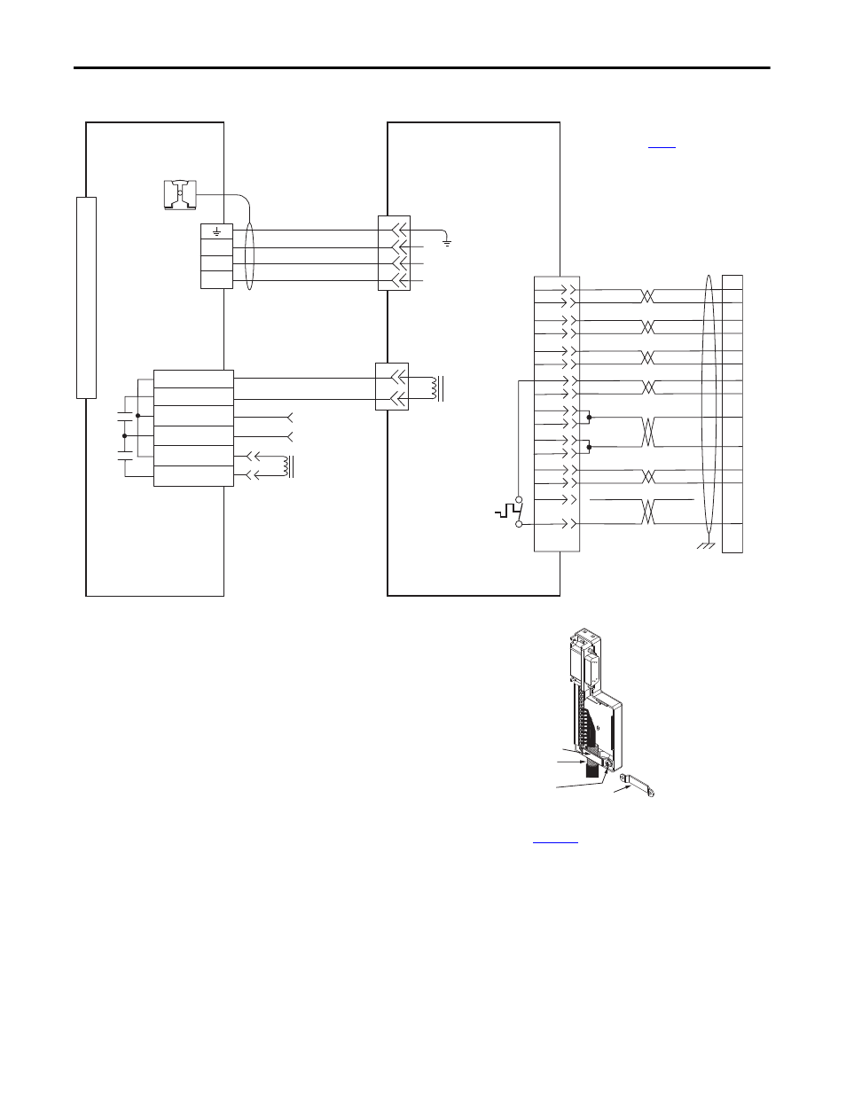
Interconnect Diagrams
Figure 105 - AM Module (230V) Wiring Example with F-Series Motors
D
C
B
A
GND
BR+
BR-
A
B
W
V
U
1
2
3
4
5
6
7
8
9
10
11
12
13
14
15
W
V
U
MBRK -
MBRK +
COM
PWR
DBRK -
DBRK +
BR+
BR-
AM+
AM-
BM+
BM-
IM+
IM-
TS+
S3
GREEN
WHT/GREEN
GRAY
WHT/GRAY
BLACK
WHT/BLACK
RED
WHT/RED
C
D
E
F
A
B
R
P
1
2
3
4
5
10
11
8
K
J
L
M
+5VDC
ECOM
14
6
N
T
H
S
BLUE
WHT/BLUE
VIOLET
WHT/VIOLET
S2
S1
13
12
6
–
TS-
6
5
4
3
2
1
4
3
2
1
Green/Yellow
1/Blue
2/Black
3/Brown
Black
White
WHT/BROWN
BROWN
Resistive Brake
Connections
Motor/Resistive
Brake (BC) Connector
Motor Power
(MP) Connector
Note 10
Note 15
Motor Feedback
(MF) Connector
User Supplied
24V DC
Cable Shield
Clamp
Motor Brake
Three-phase
Motor Power
Motor Feedback
Thermostat
F-Series (230V)
Servo Motors with
Incremental Feedback
2090-XXNFHF-Sxx
(flying-lead) Feedback Cable
Notes 16, 17
2090-XXNPH/HF-xxSxx
Motor Power Cable
Note 16
9101-0330 Brake Cable Connector Kit
Note 16
Refer to low profile connector
illustration (below)
for proper grounding technique.
Grounding Technique for
Feedback Cable Shield
Turn clamp over to hold
small cables secure.
Exposed shield secured
under clamp.
Clamp Screws (2)
Clamp
Refer to table on
page 186
for note information.
2090-K6CK-D15M
Connector Kit
2090-K6CK-D15M
Low-profile Connector Kit
IAM (inverter) or AM
Module
Refer to Low Profile Connector Kit Installation Instructions,
publicat
, for connector kit specifications.