Rockwell Automation 2094-xMxx-S Kinetix 6000 Multi-axis Servo Drives User Manual User Manual
Page 146
146
Rockwell Automation Publication 2094-UM001H-EN-P - June 2013
Chapter 6
Configure and Start the Kinetix 6000 Drive System
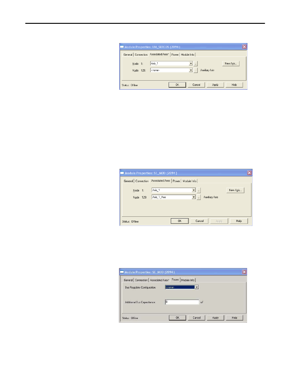
10. Assign your axis to Node 1.
11. Click Apply.
The Auxiliary Axis (Node 129) is configured identical to Node 1 by
clicking New Axis and creating a new tag.
12. Click Apply if you made changes.
13. Click the Power tab.
TIP
With drive firmware revision 1.80 or later, and the Logix Designer application or
RSLogix 5000 software, version 13 or later, it is possible to configure the
Auxiliary Axis feedback port as a Feedback Only axis. With this feature, you can
configure each IAM inverter or AM module to appear as two axes/nodes on the
sercos ring. The base node is the servo axis using the motor feedback, and the
base node (plus 128) is a feedback-only axis that uses the auxiliary feedback
port.
Auxiliary feedback is not supported by the Kinetix 6000M IDM units.