Rbm module wiring examples, Figure 121 - rbm wiring example – Rockwell Automation 2094-xMxx-S Kinetix 6000 Multi-axis Servo Drives User Manual User Manual
Page 266
266
Rockwell Automation Publication 2094-UM001H-EN-P - June 2013
Appendix G
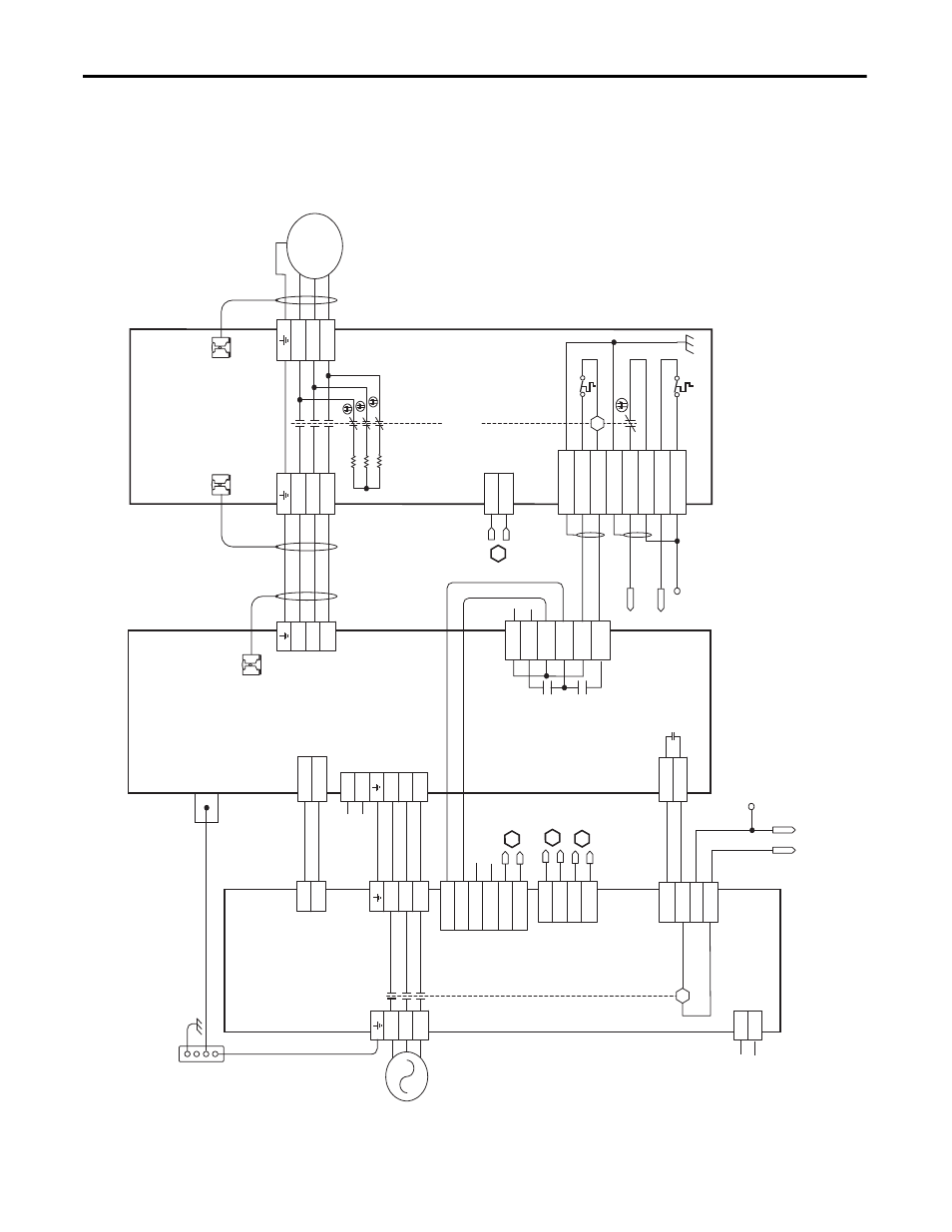
RBM Module Interconnect Diagrams
RBM Module Wiring
Examples
This example diagram shows 2094-
xCxx-Mxx-S and 2094-xMxx-S drives (with
safe torque-off ) and 2094-AL
xxS, 2094-BLxxS, and 2094-XL75S LIM modules
wired with the Bulletin 2090 RBM module.
Figure 121 - RBM Wiring Example
T2
T1
K
4
3
2
1
4
3
2
1
D
C
B
A
IO_PWR1
BRKTMP0
CONT EN-
CONT EN+
W
V
U
L3
L2
L1
2, 4, 6
8
1, 3, 5
7
DC-
DC+
L3
L2
L1
CTRL 2
CTRL 1
L3'
L2'
L1'
1
2
1
2
3
4
5
6
1
2
6
5
4
3
2
1
4
3
2
1
W_DRIVE
V_DRIVE
U_DRIVE
W_M
TR
V_M
TR
U_M
TR
SHIELD
COIL_A2
COIL_A1
SHIELD
CONST
AT_42
CONST
AT_41
TS_22
TS_21
MBRK -
MBRK +
CO
M
PWR
DBRK -
DBRK +
8
7
6
5
4
3
2
1
K
IO_C
OM1
COIL_E2
IO_PWR1
COIL_E1
BRKST
AT0
IO_PWR1
L1
L2
L3
AUX3
AUX2
AUX1
R3
R2
R1
W
V
U
GND
M
AUX4
1
2
3
4
5
6
1
2
2
1
L2
L1
IO_PWR2
IO_C
OM2
IO_PWR2
IO_C
OM2
IO_PWR2
IO_C
OM2
1
2
3
4
AUX1_L1
AUX1_L2
AUX2_L1
AUX2_L2
B
B
A
CTRL 2
CTRL 1
1
2
3
4
C
L1
L2/N
1
2
1
2
3
4
Not
e 1
Not
e 4
No
te
1
Au
xi
liar
y 230V A
C
In
pu
t (
TB
4)
Co
nnec
tor
(20
90-
XB
120-
xx
onl
y)
Kin
etix 6000
Integra
ted Axis
Module
2094-
AC
xx
-M
xx
-S or
2094-BC
xx
-M
xx
-S
(A
xi
s_
0)
Cabl
e Shi
eld
Cl
am
p
20
90-
XX
NRB
-14F0P7
RB
M t
o
D
riv
e In
ter
face
Ca
bl
e
Not
e 2
Mo
tor
C
on
nec
tio
ns
(T
B2) C
onnec
tor
Dri
ve C
onn
ec
tio
ns
(T
B1)
C
onne
ct
or
I/O C
onnec
ti
ons
(T
B3)
C
onnec
tor
Re
fe
r t
o the
wiri
ng ex
amp
les i
n
r m
ot
or po
w
er
ca
bl
e c
at
alo
g
num
bers
.
No
te
2
M
ot
or/Resi
st
iv
e
Br
ak
e (
BC
) C
onn
ec
to
r
Mot
or P
ow
er
(M
P) C
on
nec
tor
Cab
le S
hiel
d
Clam
p
Cabl
e Sh
ield
Cl
amp
Mo
to
r P
ow
er
Co
nnec
tions
Bullet
in 2090
R
esi
st
iv
e Brak
e
M
odul
e
2090-
XB
xx
-xx
(RBM_0)
Co
nt
ac
to
r Enab
le
(C
ED
) C
onnec
tor
No
te
1
Not
e 3
Co
nt
ro
l P
ow
er
(C
PD
) Co
nn
ec
to
r
Po
w
er
R
ai
l
Gr
ou
nd S
tud
DC
Bus
and
Th
re
e-
ph
as
e
Inp
ut (I
PD)
Co
nnec
tor
24V DC
O
utp
ut
(P
1L
) C
on
nec
tor
Th
re
e-
ph
as
e I
np
ut
(IP
L) C
onnec
to
r
I/O (IOL)
Co
nnec
tor
230
V A
C O
utp
ut
(P
2L
) C
on
nec
tor
Th
re
e-
ph
as
e O
ut
pu
t
(O
PL)
C
onne
ct
or
Si
ngle
-P
hase Ou
tput
(C
PL
) Co
nn
ec
to
r
Bo
nd
ed C
ab
ine
t
Gr
ou
nd Bu
s*
* Indic
at
es
User S
up
pl
ied C
omponent
Bulle
tin 20
94
Line I
n
ter
face
Module
2094-
AL
xx
S, 20
94-BL
xx
S,
or 209
4-
XL75S
-C
2
230V A
C A
ux
ili
ar
y
Inp
ut P
ower
(A
PL)
C
onne
ct
or
To
e
xt
er
na
l c
us
to
m
er
-s
up
pl
ie
d
Dr
iv
e E
na
ble
si
gn
al
.