Indic at es user s up pl ied c omponent – Rockwell Automation 2094-xMxx-S Kinetix 6000 Multi-axis Servo Drives User Manual User Manual
Page 270
270
Rockwell Automation Publication 2094-UM001H-EN-P - June 2013
Appendix G
RBM Module Interconnect Diagrams
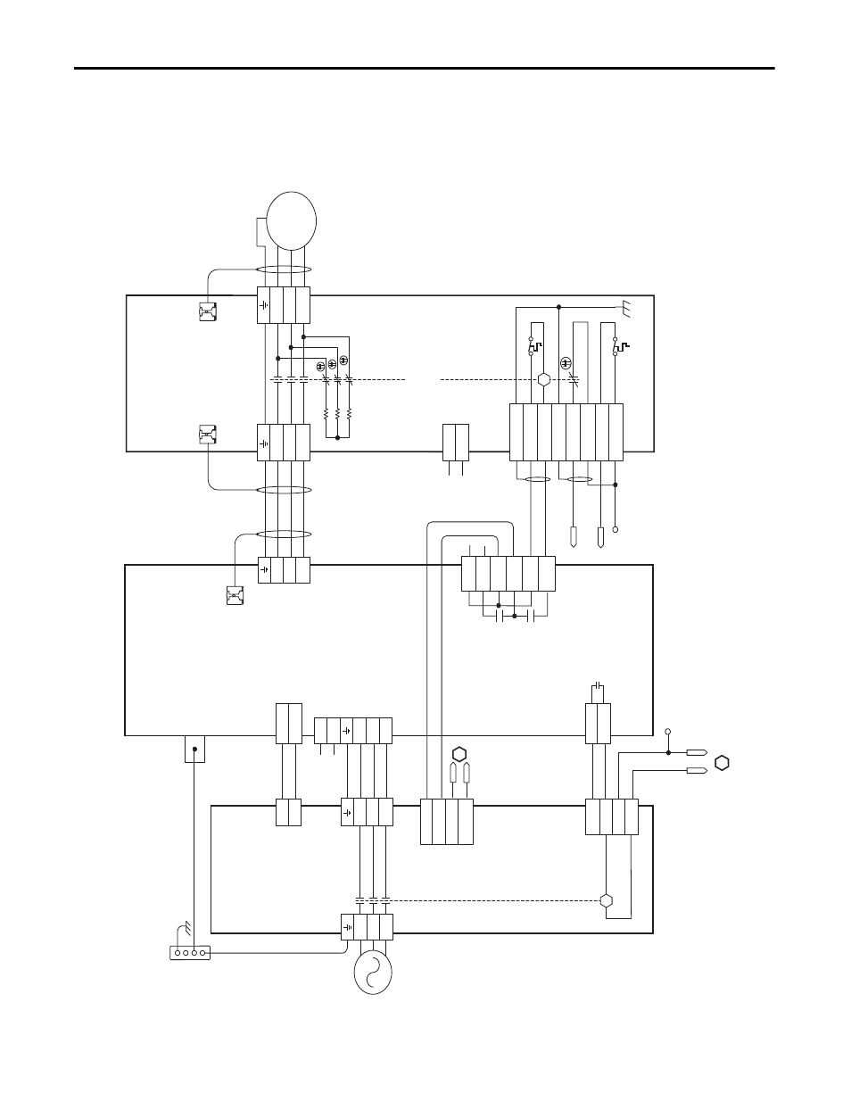
This example diagram shows 2094-
xCxx-Mxx and 2094-xMxx drives (without
safe torque-off ) and 2094-AL09 and 2094-BL02 LIM modules wired with the
Bulletin 2090 RBM module.
Figure 123 - RBM Wiring Example, Category 2 Configuration per ISO 13849-1
T2
T1
K
4
3
2
1
4
3
2
1
D
C
B
A
IO_PWR
BRKTMP0
CONT EN-
CONT EN+
W
V
U
L3
L2
L1
DC-
DC+
L3
L2
L1
CTRL 2
CTRL 1
L3'
L2'
L1'
1
2
1
2
3
4
5
6
1
2
6
5
4
3
2
1
4
3
2
1
W_DRIVE
V_DRIVE
U_DRIVE
W_M
TR
V_M
TR
U_M
TR
SHIELD
COIL_A2
COIL_A1
SHIELD
CONST
AT_42
CONST
AT_41
TS_22
TS_21
MBRK -
MBRK +
CO
M
PWR
DBRK -
DBRK +
8
7
6
5
4
3
2
1
K
BRKST
AT0
IO_PWR
L1
L2
L3
AUX3
AUX2
AUX1
R3
R2
R1
W
V
U
GND
M
AUX4
1
2
3
4
B
2
1
2
1
L2
L1
24-26
20-22
13
4
L1
L2
MBRK_PWR
MBRK_C
OM
MBRK_PWR
MBRK_C
OM
IO_PWR
IO_C
OM
COIL_A1
COIL_A2
A
Not
e 1
Not
e 4
No
te
1
Au
xi
liar
y 230V A
C
In
pu
t (
TB
4)
Co
nnec
tor
(20
90-
XB
120-
xx
onl
y)
Kin
etix 6000
Integra
ted Axis
Module
2094
-A
Cxx
-M
xx
or
209
4-BC
xx
-M
xx
(A
xi
s_
0)
Ca
bl
e S
hi
el
d
Cla
m
p
20
90-
XX
NRB
-14F0P7
RB
M t
o
D
riv
e In
ter
face
Ca
bl
e
Not
e 2
Mo
tor
C
on
nec
tio
ns
(T
B2) C
onnec
tor
Dri
ve C
onn
ec
tio
ns
(T
B1)
C
onne
ct
or
I/O C
onnec
ti
ons
(T
B3)
C
onnec
tor
Mo
to
r/
Resi
sti
ve
Br
ak
e (B
C)
C
onnec
tor
Mo
tor
P
ow
er
(MP) C
onnec
tor
Cab
le S
hiel
d
Clam
p
Cabl
e Sh
ield
Cl
amp
Mo
to
r P
ow
er
Co
nnec
tions
Bullet
in 2090
R
esi
st
iv
e Brak
e
M
odul
e
2090-
XB
xx
-xx
(RBM_0)
Co
nt
ac
to
r E
na
bl
e
(C
ED
) Co
nn
ec
to
r
No
te
1
Not
e 3
Co
nt
ro
l P
ow
er
(C
PD
) C
on
ne
ct
or
Po
w
er
R
ai
l
Gr
ou
nd
S
tu
d
DC Bus
an
d
Th
re
e-
ph
as
e
In
put
(I
PD
)
Co
nn
ec
to
r
24V DC
O
ut
put
(P
SL) C
on
ne
ct
or
Th
re
e-
ph
as
e I
npu
t
(I
PL)
C
onne
ct
or
I/O
(IOL)
Co
nne
ct
or
Th
re
e-
ph
as
e O
ut
pu
t
(O
PL)
C
onne
ct
or
Si
ngle
-P
hase Ou
tput
(C
PL
) Co
nn
ec
to
r
Bo
nde
d C
ab
ine
t
Gr
ou
nd Bu
s*
* Indic
at
es
User S
up
pl
ied C
omponent
B
ulletin
20
94
Line
Inte
rfac
e
Modu
le
2094-
AL09
and 2094-
BL02
Re
fe
r t
o
th
e wir
ing
e
xa
m
pl
es in
A f
or
m
ot
or
po
w
er
ca
bl
e ca
ta
lo
g n
um
ber
s.
Not
e 2