Table 3-1. sampling time intervals, 8 datalink – Micromod Micro-DCI: 53MC5000 Multi-Loop Process Controller Instruction Manual User Manual
Page 87
If the BACKGROUND SCAN INDEX is left at one, the display will be updated with each control
algorithm execution because it will be determined solely by the SCAN INDEX. A number greater than
one configured into the BACKGROUND SCAN INDEX causes that many control algorithm updates to
occur before the display is updated with new data.
There is a standard display algorithm for each display of the 53MC5000 Process Control Station.
(The controller displays are covered in detail in Section 4.) If the controller has
extended function-
ality (model number 53MC5
♦♦
2 etc., where
♦
is a selectable item), F-TRAN can be used to create
personalized display algorithms to supplement the standard display complement. The display is
generated when the microprocessor interprets the active display algorithm to produce a pattern in
memory which corresponds to the elements in the display. This pattern is then transferred into a
special memory which can be accessed by two processors. Here a second processor uses the
contents of the memory to light individual elements in the display. The dynamics of the display
require that each element be on only a fraction of a second. Therefore, to give the appearance of
being continuously lit, the second processor refreshes the screen by turning the individual elements
on and off 80 times a second.
The horizontal and vertical keypads are scanned 20 times a second (every 50 ms). When a key is
detected as being pressed, that information is temporarily stored for synchronization with the control
algorithms and display processing. If a slewing key is pressed (setpoint up arrow, etc.), the
appropriate database location is manipulated. For controllers with multiple loops, e.g., 2 loop or 4
loop controllers, a pointer appears on the display to identify which algorithm is affected by the keypad
push buttons. The pointer directs the keypad inputs to the individual control algorithm databases.
The pointer is shifted from one loop to another with a push button on the vertical keypad.
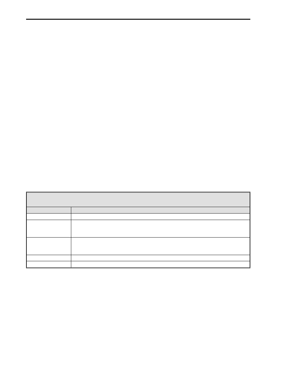
A summary of the sampling time intervals is provided in Table 3-1 as follows:
Table 3-1. Sampling Time Intervals
Time Interval
Event
50 ms
Analog and digital input signal sampling.
50 ms - 1500 ms
Input signals are digitally processed through user selected algorithms (50 ms =
1/20 s = SCAN INDEX set to 1. 1500 ms = 1 1/2 seconds = SCAN INDEX set
to 30).
1 s
Time between successive trend and totalizer updates. Each trend and each
totalizer is updated sequentially in ascending order every 50 ms. Trends are
updated first, then totalizers.
80 times/s
Display elements are turned on and off to refresh the screen.
50 ms
Keypads are scanned.
3.8 DATALINK
The Datalink port is at the rear of the unit on either the Standard Rear Terminal Board (pins 19
through 22) or the optional Cord Set Connector Board (J10 and J11). It provides the standard
RS-485 MICRO-DCI multidrop network connection. A personal computer with the appropriate soft-
ware application package loaded and running (see the table of software application packages in
Section 3.2) can function as the network server and therefore be a central operating station for the
network. The maximum data transfer rate for a Datalink network is 28,800 baud.
53MC5000 Process Control Station
3-4