Table 5-3. database modules – Micromod Micro-DCI: 53MC5000 Multi-Loop Process Controller Instruction Manual User Manual
Page 149
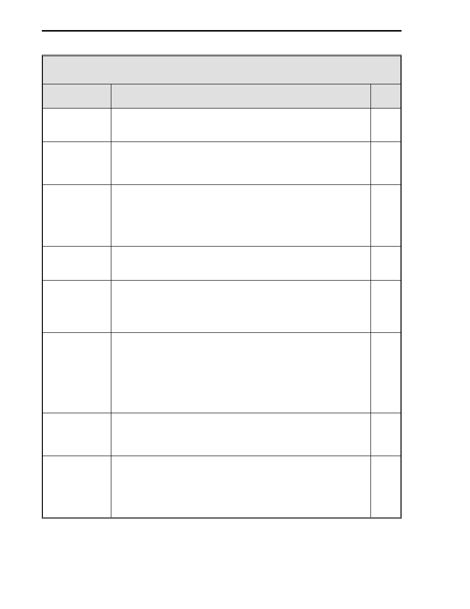
Table 5-3. Database Modules
Name
Purpose
See
Table
Discrete Out
Modules
These modules allow the action of a DOs to be reversed (normally a
closed contact = 1, but can be changed to = 0). The 18 Contact
Closure Output (DO0-17) Modules can be configured separately.
5-7
External
Module
This module provides the ability to transfer data to/from other MICRO-
DCI controllers or instruments through the MicroLink peer-to-peer
communications network. It provides 24 (0-23) tasks, each capable of
performing a read, write, or bidirectional operation.
5-8
Control
Modules
The primary purpose of these modules are to affect the action of the
control algorithms and the content of the control loop displays. They
are used to set the controller’s responsiveness, Alarm Limits 1 & 2,
Alarm Dead Band, and the range limits (e.g., 0 - 100, -20 - 80.), etc.
There are four Controller Modules (CON0-3) that can be configured
separately, one for each control loop display.
5-9
Status
Modules
There are two Status Modules that can be configured separately.
Each module displays eight logical status indicators that can also
generate alarms when enabled.
5-10
Parameter
Modules
These modules provide quick push button display access to any three
selected datapoints for viewing or modifying (e.g., Alarm Limits 1 & 2
and Alarm Dead Band) without the necessity of entering Engineer
mode and addressing the datapoints. There are eight Parameter
Display Modules that can be configured separately.
5-11
Trend Modules
There are eight Trend Modules that can be configured separately.
Each Trend Module provides storage of the last 80 samples of the
specified input. The first four Trend Modules can be attached to the
four CON Modules if the Trend Rate datapoint in the appropriate CON
Module is non-zero. When a Trend Module is attached to its
appropriate CON Module, height, rate, mode, span, zero, and
designator parameters are overwritten with values from the CON
Module.
5-12
Totalizer Modules There are eight totalizer modules that can be configured separately.
Each module provides a
totalization (integration) of a specified input.
Sampling occurs once a second, whenever the input parameter
contains a valid datapoint specification.
5-13
System Module
This module contains unit level parameters for controlling overall
operations as well as selecting and enabling various features. It is
used to select the desired controller operating algorithm and execute
rate, build the display list, configure Datalink, Microlink, and gateway
parameters (to configure the MicroLink and gateway parameters, see
Instruction Bulletin 53MC9011, Revision 2, MicroLink.)
5-14
2 of 2
53MC5000 Process Control Station
5-4