0 cs3 - ratio (pid) controller, 1 cs3 - ratio (pid) controller – Micromod Micro-DCI: 53MC5000 Multi-Loop Process Controller Instruction Manual User Manual
Page 204
8.0 CS3 - RATIO (PID) CONTROLLER
8.1 CS3 - RATIO (PID) CONTROLLER
The Ratio (PID) Controller is used where one variable, called the controlled variable, must be auto-
matically maintained in definite proportion to another variable, called the wild variable. Field trans-
mitters (e.g, flow meters) must be installed in each variable line. Signals from the controlled and
wild variable transmitters (AI0 and AI1 respectively) are received by the Ratio Controller which
compares them and calculates the required correction that is applied as an output signal (AO0) to
a final control element (e.g., valve) in the controlled variable line. The final element in the con-
trolled variable line is moved to alter line throughput so that the predetermined ratio between the
two lines is maintained. The predetermined ratio is set at the controller faceplate with the Ratio/Lo-
cal (R/L) push button in
R. While in Ratio control, the setpoint push buttons are used to set the de-
sired ratio value which alters the K1 term in the setpoint calculation expression. Altering the ratio
value also causes the ratio tick-bar on the display to move. The ratio tick-bar is immediately cov-
ered by the setpoint arrow indicator when the setpoint push button is released. Because the K1
value is part of the setpoint calculation expression, altering the ratio setting indirectly affects the
setpoint value. When the R/L push button is in Local (
L) control, the setpoint push buttons modify
only the setpoint value. In Local control, the controlled variable line functions as a standard Single
Loop (PID) Controller (see Section 6).
To minimize sudden process changes, adjust the local
setpoint value to cause the setpoint indicator to cover the ratio tick-bar before switching to
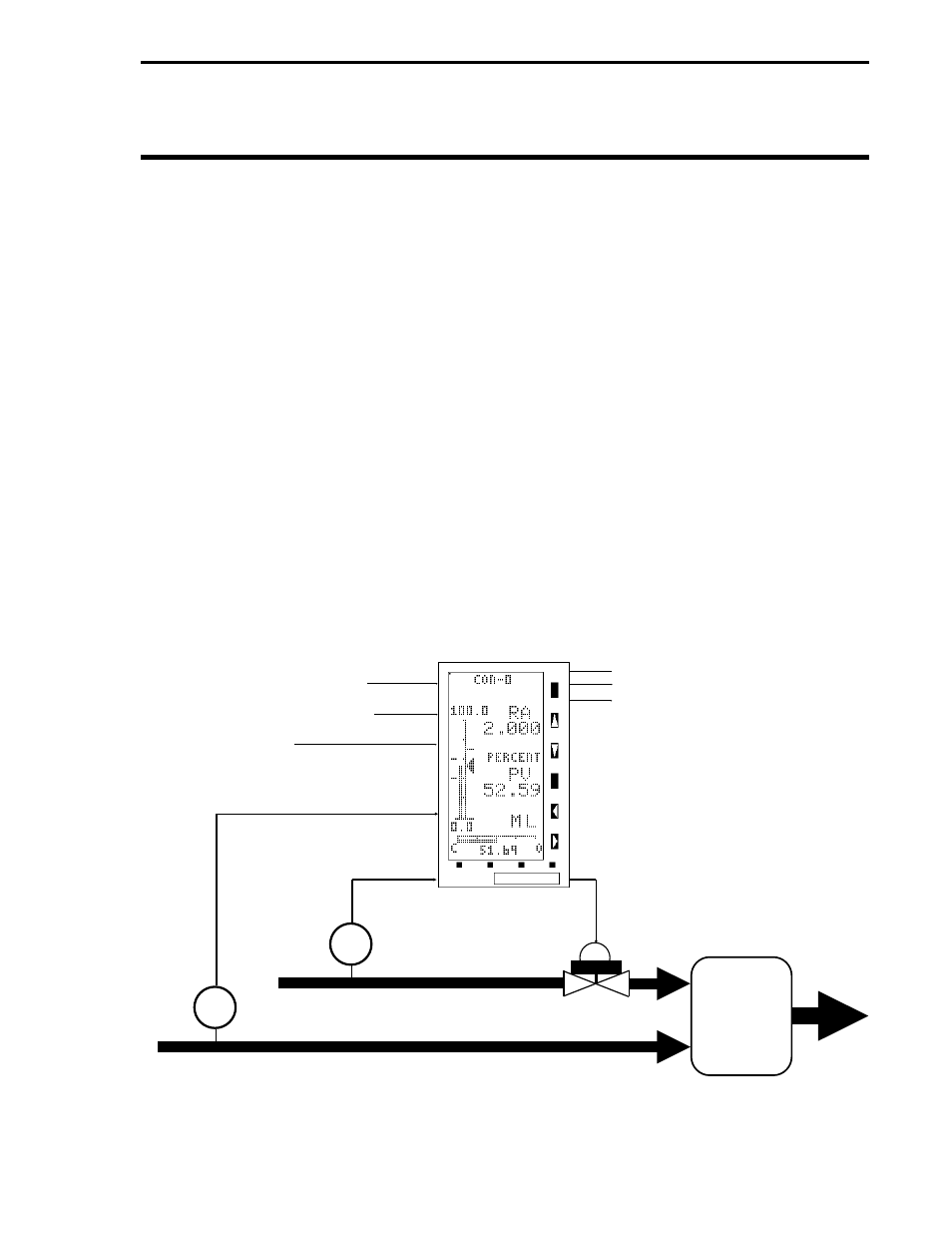
ratio control. A typical low-resolution display Ratio (PID) Controller is illustrated in Figure 8-1.
Figure 8-1. Typical CS3 Ratio Controller Application
VALVE
BLENDING
PHASE OF
PROCESS
AI0 - CONTROLLED
VARIABLE
FT
AI2 - ADDITIVE FEED FORWARD
DI0 - FORCE OUTPUT TRACKING
(OPEN CONTACT)
DI1 - RATIO ENABLE
(CLOSED CONTACT)
AI1 - WILD VARIABLE
AO1 - NOT USED
DO0 - PROCESS ALARM 1
DO1 - PROCESS ALARM 2
AO0 CONTROL
OUTPUT
FT
WILD LINE
CONTROLLED LINE
Section 8. CS3 - Ratio (PID) Controller
8-1