Table 1-3. dual relay itb specifications – Micromod Micro-DCI: 53MC5000 Multi-Loop Process Controller Instruction Manual User Manual
Page 29
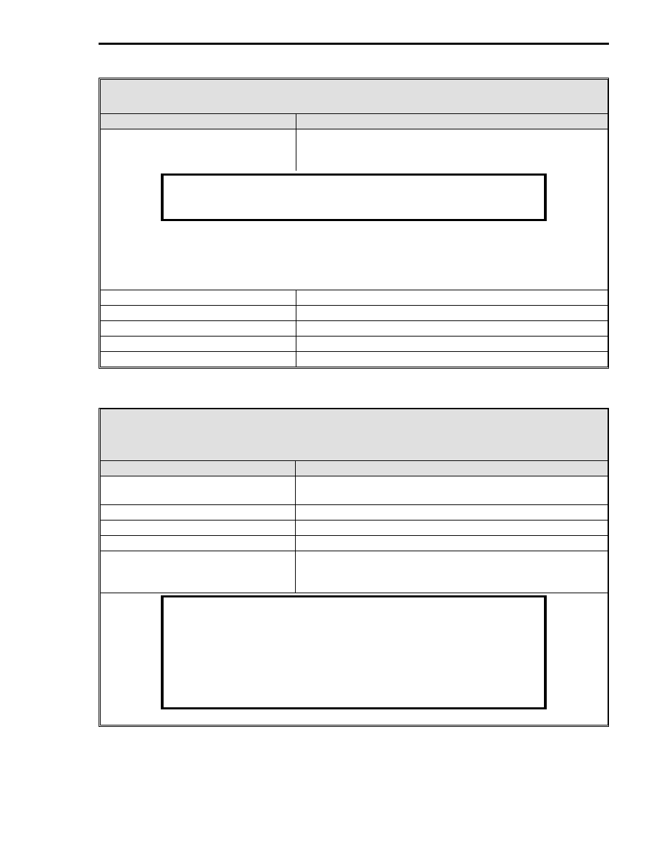
Table 1-3. Dual Relay ITB Specifications
Item
Specification(s)
Safety classification
FM Approved: Nonincendive for Class 1, Div. 2, Group A,
B, C, & D hazardous locations.
WARNING
For use in Division 2 locations, the energy to relay contacts 8 and 11
must be limited to < 3 VA, < 28 V and 250 mA, resistive loads only.
The use of open contact type relays in a Class 1, Division 2 location is permitted only if the
energy switched by the contacts is limited to an intrinsically safe level. It is the user’s
responsibility to limit the energy.
Dimensions
3.5 in. (89 mm) long, 2.740 in. (70 mm) wide.
Number of outputs
2
Operational type
SPDT
External power requirements
+24 V, 35 mA for each relay.
Contact rating
10 Amps Resistive, 1 Amp Inductive, 250 V ac maximum.
Table 1-4. 16 Digital Input/Digital Output Option Board and ITB
Specifications
Item
Specification(s)
Safety classification
FM Approved: Nonincendive for Class 1, Div. 2, Group A,
B, C, & D hazardous locations.
Dimensions
11 in. (279.40 mm) long, 2.740 in. (70 mm) wide.
Maximum number of inputs/outputs
16
Operational type
OPTO 22 modules.
External power requirements
5 V @ 224 mA
24 V @ 420 mA
NOTE
When using this option, the 16 inputs and 16 outputs are mapped into
DI2-17 and DO2-17 respectively (32 total). Any mix of 16 I/O modules
can be installed; however, positions having input modules installed
must have the corresponding output DO bit set to 0. For example, if
the first module position (M1) is an input module, the DO2 bit (L026)
must be configured to 0 to indicate it is not an output module. The
status of the input module will be reflected in the DI2 bit (L002).
Section 1. Introduction
1-15