0 cs2 - analog backup controller, 1 cs2 - analog backup controller – Micromod Micro-DCI: 53MC5000 Multi-Loop Process Controller Instruction Manual User Manual
Page 196
7.0 CS2 - ANALOG BACKUP
CONTROLLER
7.1 CS2 - ANALOG BACKUP CONTROLLER
The Analog Backup Controller is used in operations where a remote computer is normally control-
ling the final element directly. In this process configuration, the controller functions as a signal se-
lector and automatic backup unit to the computer. The controller assumes process control in the
event of a signaled computer failure. The Analog Backup Controller operates as a Single Loop
(PID) Controller (see Section 6) when driving the process final element (e.g., output valve). While
in backup and automatic, the controller continually adjusts its output to match the AI3 Control Ele-
ment Feedback signal so that transfer to online operation is bumpless in the event of computer fail-
ure. Selection of the computer or backup controller signals to the process final element is
performed by the controller’s DO modules (DO1 and DO2) in conjunction with blocking diodes (see
circuit diagram on next page). The computer drives the final process element when remote opera-
tion is selected at the controller faceplate with the R/L push button and if the contact of DI0 is
closed; otherwise, the computer’s control signal is diverted and the output from the controller is the
active signal to the process final element. AO1 indicates whether the computer or the controller is
driving the final element (20 mA output = computer, 4 mA output = controller). Unless DI1 input is
closed, the controller is not permitted to operate in automatic mode. A typical low-resolution dis-
play Analog Backup Controller is illustrated in Figure 7-1, and the DO Output Diverter Circuit is il-
lustrated in Figure 7-2.
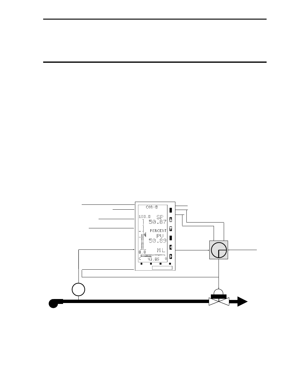
Figure 7-1. Typical CS2 Analog Backup Controller Application
PUMP
VALVE
HOST
COMPUTER
DIVERTER (SEE
FIGURE 7-2)
AI3 - CONTROL
ELEMENT FEEDBACK
FT
AI1 - NOT USED
AI2 - ADDITIVE FEED FORWARD
DI0 - COMPUTER READY
(CLOSED CONTACT)
DI1 - AUTO ENABLE
(CLOSED CONTACT)
AI0 - PROCESS VARIABLE
AO1 - COMPUTER CONTROL STATUS
DO0 - COMPUTER OUTPUT DIVERTER
DO1 - BACKUP OUTPUT DIVERTER
AO0
BACKUP
CONTROL
OUTPUT
Section 7. CS2 - Analog Backup Controller
7-1