Table b-2. message field definitions – Micromod Micro-DCI: 53MC5000 Multi-Loop Process Controller Instruction Manual User Manual
Page 342
B.1.2 PROTOCOL
The Datalink protocol requires the host or SUPERVISOR-PC to initiate all transactions. There are
two basic categories for all of the Datalink message types:
Interrogate , which is used to read
data from an addressed controller, and
Change, which is used to alter a value in an addressed con-
troller. The addressed controller decodes the message and provides an appropriate response.
The protocol definitions for the Datalink message types are provided in Table B-2.
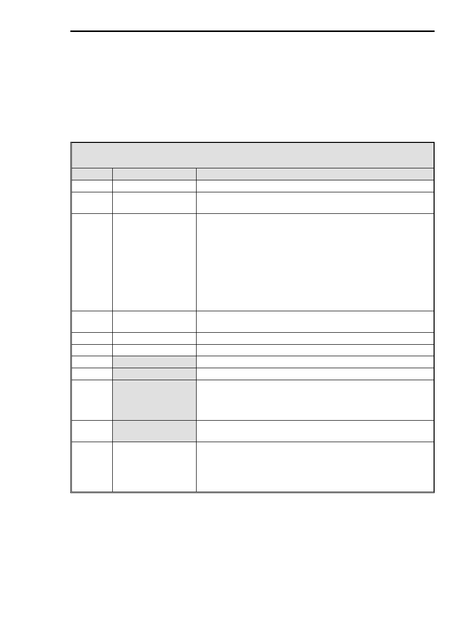
Table B-2. Message Field Definitions
Atom
Title
Definition
SOH
Start of Header
This character, 7E, denotes the beginning of a message.
I.A.
Controller Address
The address of the controller responding to the transaction. It
must be within a range of 00-1F (00-31 decimal).
CMD
Command
Is the operation to be performed or a description of the
message that follows the Command-I.A. byte. The Command-
I.A. byte has two fields: the Command field (3 bits), and the
I.A. field (5 bits). There are five commands, listed as follows:
Interrogate
Change
Change Bits
Acknowledge
Response
The commands are covered in Section B.1.3, Message Types.
NUM
Number
The number of data bytes transferred or requested. The NUM
must be in a range of 00-32 decimal.
LO-ADD
Lower Address Bits
The least significant 8 bits of a 16 bit controller address.
HI-ADD
Higher Address Bits
The most significant 8 bits of a 16 bit controller address.
DATA
An 8 bit data byte.
XXXX
Represents a variable number of data bytes.
MASK
An 8 bit byte where each bit, called a flag, is dedicated to an
event that is permitted or prohibited, depending on the flag
setting. If the flag is set to
0, the event is permitted. If the flag
is set to
1, the event is prohibited.
STATE
Represents the bit settings of a particular byte: which bits are
set to
1, and which bits are set to 0.
LRC
Longitudinal
Redundancy
Character
Is a character written at the end of the message that
represents the byte content of the message and is checked to
ensure data was not lost in transmission. It is the sum of all
bytes Modulo 256 of the message not including the SOH
character or its own bit settings (LRC).
Appendix B. Communications
B-3