6 removable plug-in connectors – Micromod Micro-DCI: 53MC5000 Multi-Loop Process Controller Instruction Manual User Manual
Page 50
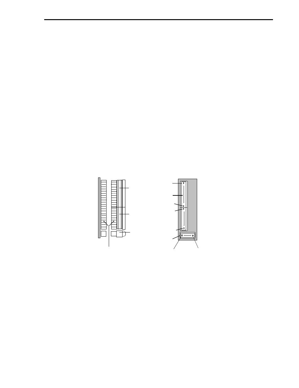
2.6 REMOVABLE PLUG-IN CONNECTORS
The controller with standard rear terminal board (not the cord set option) has a vertical terminal
strip (TB1) for signal connections and a horizontal terminal strip (TB2) for power input wiring. Both
terminal strips have removable plug-in connectors. As shown in Figure 2-10, the upper signal con-
nector for TB1 has screw lugs 1 through 12 and the lower signal connector has screw lugs 13
through 22. All of the screw lugs for TB2 are on a single power connector.
To remove a signal connector from TB1, grasp it firmly on both sides with the thumb and forefinger,
rock it gently from top to bottom (not side to side) and pull it straight out.
To remove the power connector from TB2, grasp it firmly with the thumb and forefinger, rock it gen-
tly from side to side and pull it straight out.
Each connector is keyed and has one scalloped side as an aid to proper insertion alignment after
the wires are connected.
The screw lugs for the plug-in connectors on the back of the controller are designed for 12 - 24
AWG wire. The wire should be stripped to expose 1/4 inch (6.4 mm) of conductor before installa-
tion.
All wiring to the controller rear terminal board screw lugs is supplied by the customer.
Figure 2-10. Removable Plug-In Connectors from Standard Rear
Terminal Board
12 SIGNAL
CONNECTO
10 SIGNAL
CONNECTO
POWER
CONNECTO
SCALLOPED SIDES OF
CONNECTOR
SIDE
BACK
TO REMOVE SIGNAL CONNECTOR, GRASP SIDES
FIRMLY WITH THUMB AND FOREFINGER, ROCK
GENTLY FROM TOP TO BOTTOM (NOT SIDE TO SIDE)
LUG 1
LUG 12
LUG 13
LUG 22
LUG 1
LUG 5
TO REMOVE POWER CONNECTOR, GRASP SIDES
FIRMLY WITH THUMB AND FOREFINGER, ROCK
GENTLY FROM SIDE TO SIDE AND PULL STRAIGHT
OUT.
NOTE: REMOVABLE PLUG-IN CONNECTORS ON
TB1
TB2
Section 2. Installation
2-11