4 calibration – Micromod Micro-DCI: 53MC5000 Multi-Loop Process Controller Instruction Manual User Manual
Page 320
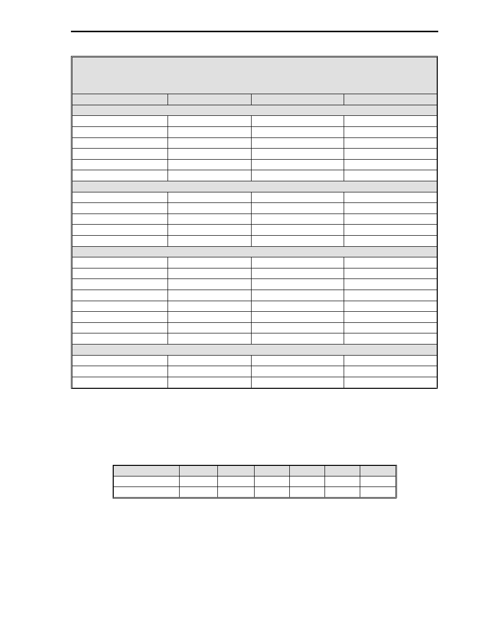
Table 18-4. Isolated Discrete I/O Modules for the
16DI/DO ITB
OPTO 22 Part Number
ITB Voltage
Max. Input Current
Input Voltage Range
OPTO 22 AC Input Modules
G4IDC5
5 V dc
25 mA
12-32 V ac
G4IDC5G
5 V dc
25 mA
35-60 V ac
G4IAC5
5 V dc
11 mA
90-140 V ac
G4IAC5A
5 V dc
6.5 mA
180-280 V ac
G4IDC24
24 V dc
25 mA
10-32 V ac
G4IAC24
24 V dc
11 mA
90-140 V ac
OPTO 22 AC Output Modules
G4OAC5
5 V dc
3 A
12-140 V ac
G4OAC5A
5 V dc
3 A
24-280 V ac
G4OAC5A5 (NC)
5 V dc
3 A
24-280 V ac
G4OAC24
24 V dc
3 A
12-140 V ac
G4OAC24A
24 V dc
3 A
24-280 V ac
OPTO 22 DC Input Modules
G4IDC5
5 V dc
25 mA
10-32 V dc
G4IDC5B
5 V dc
45 mA
4-16 V dc
G4IDC5D
5 V dc
30 mA
2.5-28 V dc
G4IDC5G
5 V dc
6 mA
35-60 V dc
G4IAC5
5 V dc
11 mA
90-140 V dc
G4IAC5A
5 V dc
6.5 mA
180-280 V dc
G4IDC24
24 V dc
25 mA
10-32 V dc
G4IAC24
24 V dc
11 mA
90-140 V dc
OPTO 22 DC Output Modules
G4ODC5
5 V dc
3 A
5-60 V dc
G4ODC5A
5 V dc
1 A
5-200 V dc
G4ODC24
24 V dc
3 A
5-60 V dc
18.4 CALIBRATION
The controller’s
analog inputs (AI0-3) and analog outputs (AO0&1) normally do not require
recalibration. If it becomes necessary to recalibrate the controller due to the inadvertent change of
the stored calibration values, then this can be accomplished by altering their respective datapoints.
The calibration zero and span datapoint locations are as follows:
AI0
AI1
AI2
AI3
AO0
AO1
Calibrate Zero
B263
B264
B265
B266
B267
B268
Calibrate Span
C296
C297
C298
C299
C300
C301
Note: The spans have a nominal value of 1.0 and can be adjusted
up or down within the range of 0.8 to 1.2. The zeros have a nom-
inal value of 128 and can be adjusted up or down within the range
of 100 to 150.
Section 18. Maintenance and Parts List
18-11