Figure 4-4. point display 3 (cdm = 1, indicator) – Micromod Micro-DCI: 53MC5000 Multi-Loop Process Controller Instruction Manual User Manual
Page 129
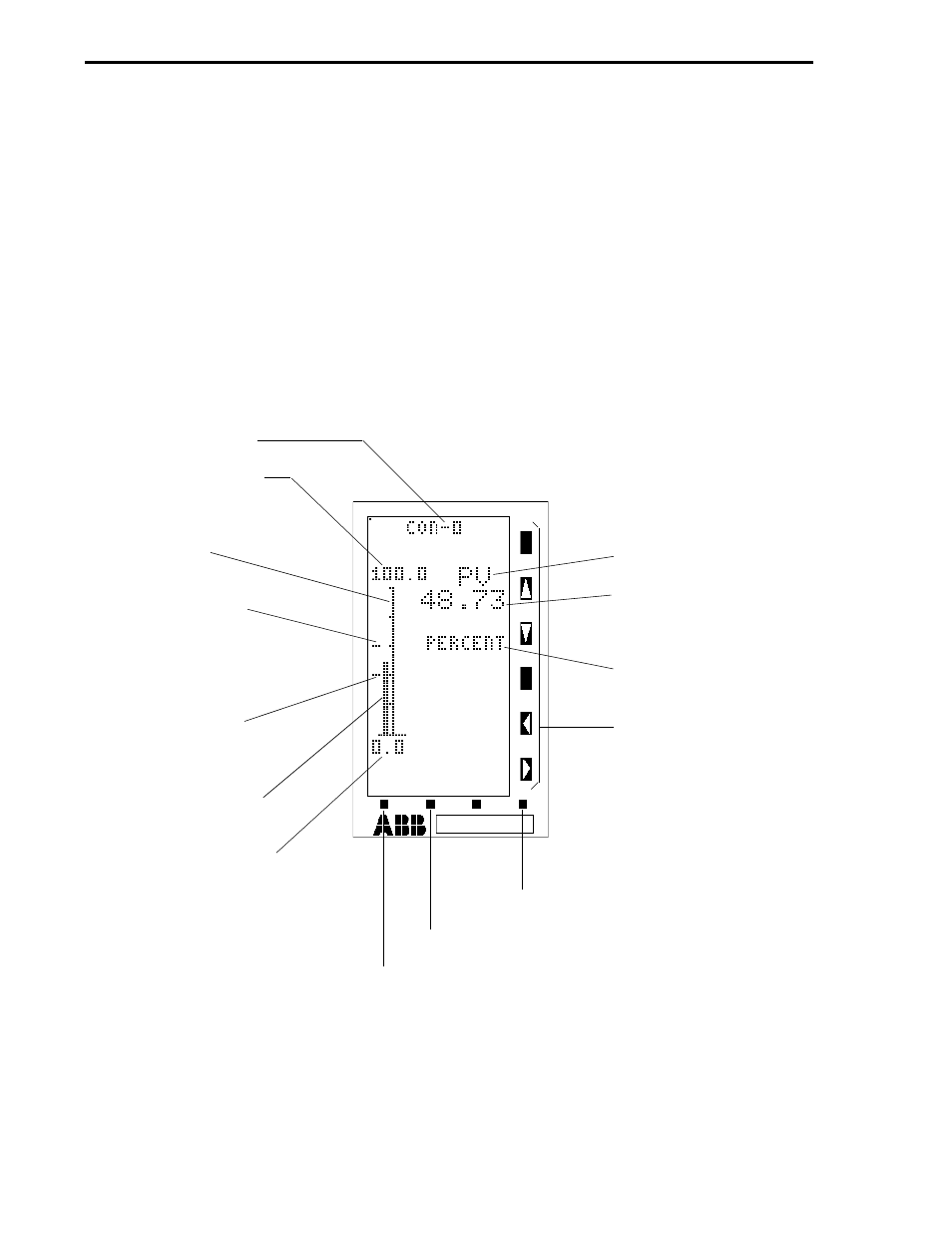
4.3.2 POINT DISPLAY 3 (CDM = 1, INDICATOR)
The Indicator display is illustrated in Figure 4-4 In the illustration the control module tag name
appears at the top of the display. The left side of the Indicator display (CDM = 1) contains a fifty
segment vertical axis. Above and below the vertical axis are the numeric values indicating the upper
and lower ranges. Left of the vertical axis is the process variable bar. When alarm limits are
configured, they appear left of the process variable bar as indicators at the alarm limit values. On the
right side of the display are the process variable (PV) legend, process variable value (e.g., 48.73
shown in the illustration), and the engineering units legend. (Unless configured otherwise, PER-
CENT is the default for the engineering units legend.) If the process variable bar moves beyond
either alarm limit indicator, an alarm overlay appears in the area immediately below the control
module tag name that indicates the alarm type. The faceplate vertical keypad push buttons have no
affect on the Indicator display (R/L,
⇑
,
⇓
, A/M,
⇐
, and
⇒
push buttons are not applicable).
Figure 4-4. Point Display 3 (CDM = 1, Indicator)
CONTROL MODULE
TAG NAME (A000)
CONTROLLER SPAN
(C115) + CONTROLLER
LOWER RANGE (C116)
50 SEGMENT
VERTICAL AXIS
HIGH ALARM LIMIT
INDICATOR - CON0
ALARM LIMIT 1 (C103)
(ALSO CONTROL
ALARM MODE, B335 = 0)
LOW ALARM LIMIT
INDICATOR - CON0
ALARM LIMIT 2 (C104)
PROCESS VARIABLE
BAR
CONTROLLER LOWER
RANGE (C116)
PROCESS VARIABLE
LEGEND
PROCESS VARIABLE
VALUE
ENGINEERING UNITS
(A001)
NOT APPLICABLE
MODE - ALARM RESET
F2 - PAGE IN LIST OR PAGE FORWARD
F1 - NEXT DISPLAY GROUP OR PAGE BACK
53MC5000 Process Control Station
4-16