Micromod Micro-DCI: 53MC5000 Multi-Loop Process Controller Instruction Manual User Manual
Page 28
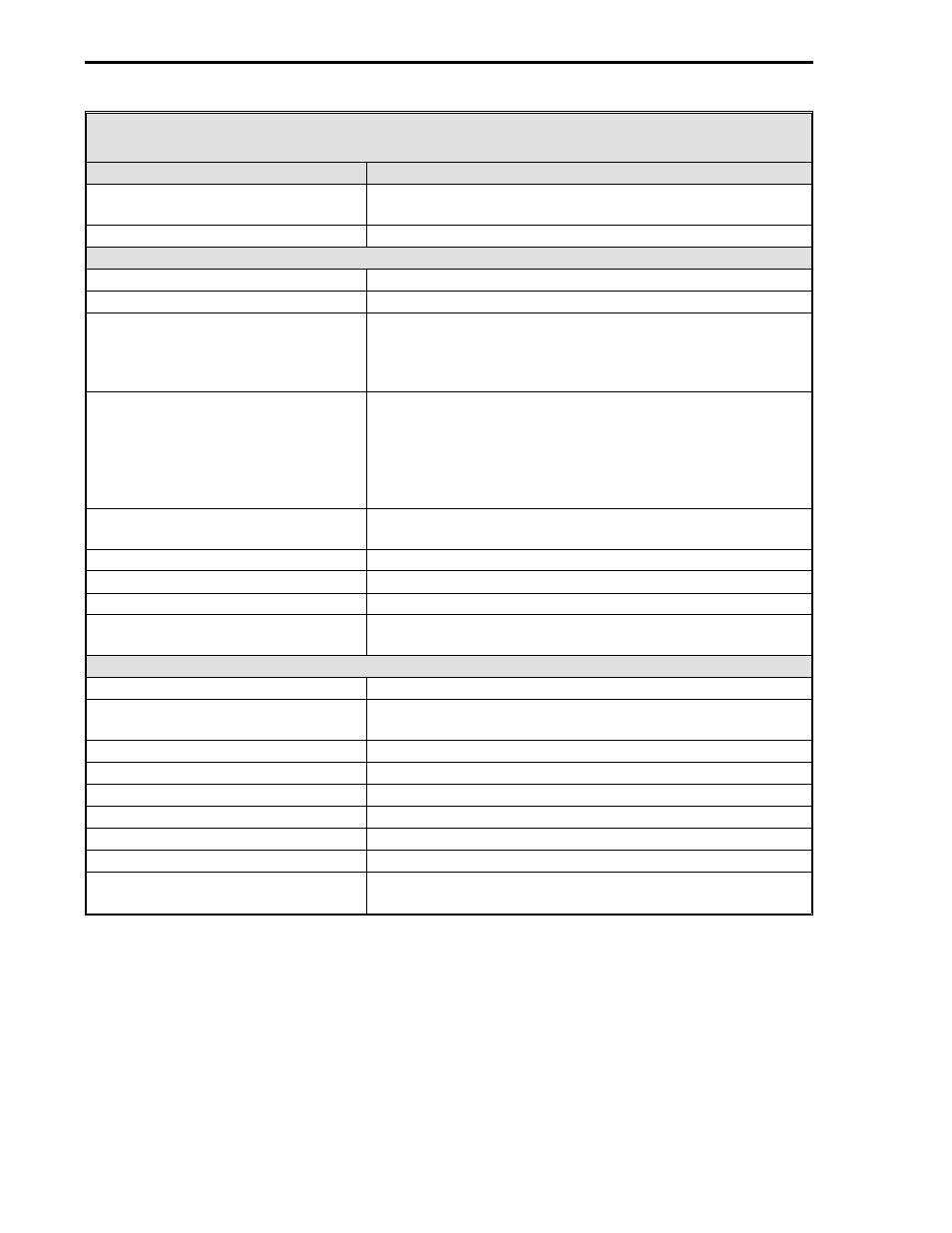
Table 1-2. 6 Digital Input/4 Digital Output Option Specifications
Item
Specification(s)
Safety classification
FM Approved: Nonincendive for Class 1, Div. 2, Groups A,
B, C & D hazardous locations.
Dimensions
8.25 in. (210 mm) long, 2.740 in. (70 mm) wide.
Contact Input Specifications (DI2 - DI7)
Number of inputs
6
Operational type
Optically-coupled phototransistors.
Input connections:
Voltage input mode
Contact input mode
2 terminals (+ and -) for each input.
2 terminals for each input (one is common).
Recognition level:
Voltage input mode
Contact input mode
Energized: 12 to 26 V dc range, 50 ohm maximum
resistance. Non-energized: 1 V dc maximum.
Energized: 500 ohms maximum, 22 to 26 V dc range. Non-
energized: 60 k ohms minimum, 26 V dc maximum.
External power requirements
24 V dc 180 mA. Only required when using contact input
mode DIs.
Recognition time
50 milliseconds
Maximum input voltage
26 V dc
Common mode limit
50 V with respect to chassis ground.
Transient immunity (all circuits)
ANSI C37.90a-1974/IEEE Std 472-1974: Ring Wave: 1.5
MHz, 3 kV, 60 pulses/s for 2.0 seconds.
Contact Output Specifications (DO2 - DO5)
Number of outputs
4
Operational type
Form A, SPST, normally open, optically isolated MOSFET
switch.
ON resistance
15 ohms maximum.
Load voltage limit
50 V dc or peak ac.
Load current
150 mA
OFF state leakage current
1 mA maximum.
Common mode limit
50 V with respect to chassis ground.
Contact protection
250 mA fuse
Transient immunity (all circuits)
ANSI C37.90a-1974/IEEE Std 472-1974: Ring Wave: 1.5
MHz, 3 kV, 60 pulses/s for 2.0 seconds.
53MC5000 Process Control Station
1-14