3 cs21 standard displays, 4 cs21 datapoint configuration selections – Micromod Micro-DCI: 53MC5000 Multi-Loop Process Controller Instruction Manual User Manual
Page 242
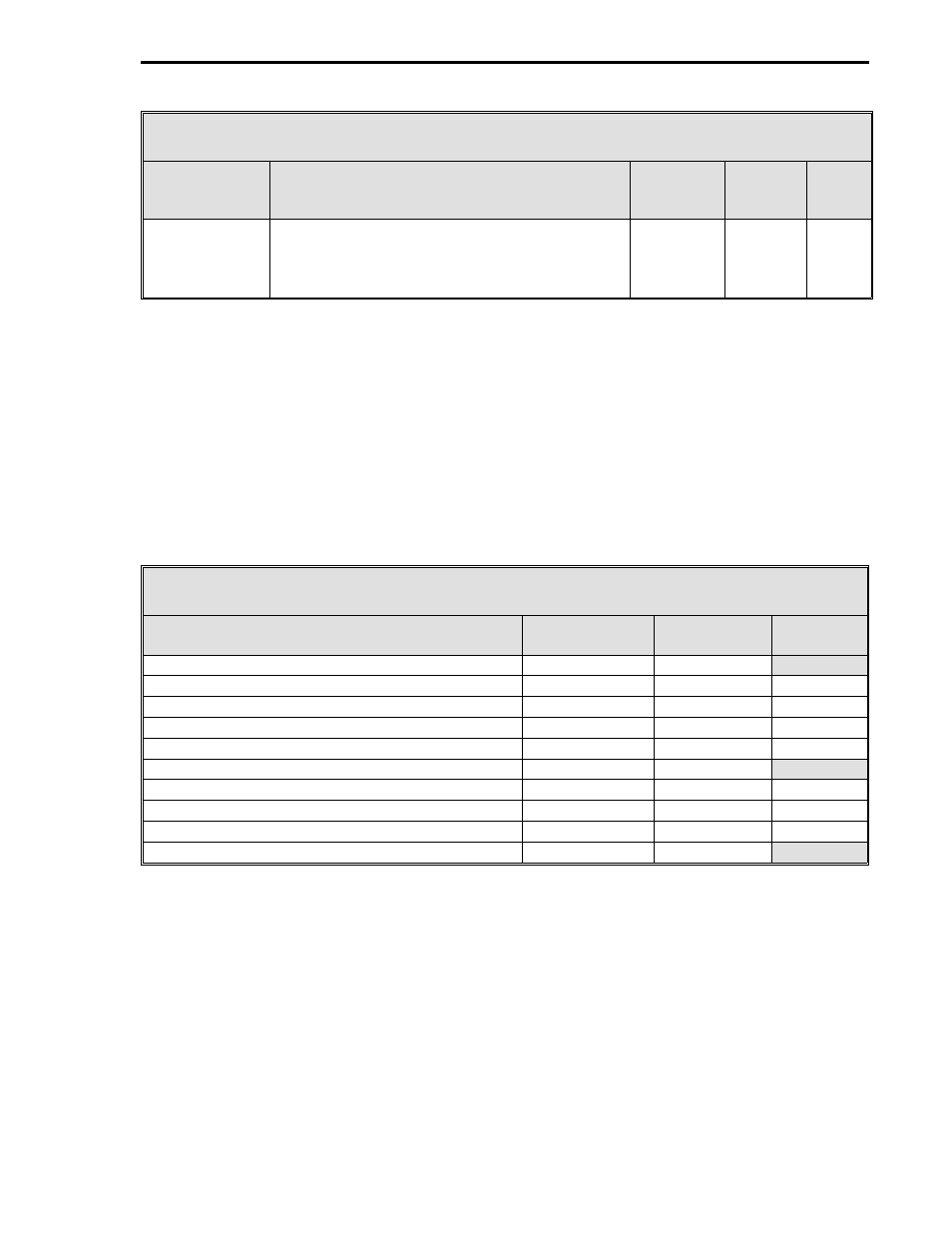
Table 12-1. CS21 Control Signals
Control
Signal
Definition
Cord
Set
ITB
Rear
Term
Board
Signal
DO1 - Process
Alarms
Primary
This contact is closed when the primary loop
Process Variable value is not within the C139
and C140 datapoint values (primary loop Alarm
Limits 1 and 2); otherwise, the contact is open.
TB2-7 (+)
TB2-8 (-)
18 (+)
17 (-)
DO1
PC
12.3 CS21 STANDARD DISPLAYS
Loading CS21 preconfigures the System Module display list for ten displays. The ten displays are
listed in Table 12-2 with appropriate reference sections, figure numbers, and configuration tables.
A configuration table is not listed for the Two Loop CON0 and CON1 display, as that information is
provided in this section. To configure the Horizontal Trend, Parameter, and System Status dis-
plays, reference the Section 4 and Section 5 information listed in the table. The Single Loop
CON0 and Single Loop CON1 displays will automatically be configured when the Two Loop CON0
and CON1 display is configured, with the exception of the Reverse Valve and Engineering Units
datapoints. These datapoints will also be covered in this section with the Two Loop CON0 and
CON1 display information.
Table 12-2. CS21 Standard Displays
Title
See
Section
Section 4
Figure
Section 5
Table
Single Loop CON0
4.3 and 4.3.1
4-3 sheet 1
Single Loop CON0 with Horizontal Trend
4.5
4-10 sheet 2
5-9
Parameter Module 0 - PID datapoints
4.6
4-11
5-11
Parameter Module 1 - Alarm Limits
4.6
4-11
5-11
System Status
4.2
4-2
5-15
Single Loop CON1
4.3 and 4.3.1
4-3 sheet 1
Single Loop CON1 with Horizontal Trend
4.5
4-10 sheet 2
5-9
Parameter Module 5 - PID datapoints
4.6
4-11
5-11
Parameter Module 6 - Alarm Limits
4.6
4-11
5-11
Two Loop CON0 and CON1
4.4
4-9 sheet 2
12.4 CS21 DATAPOINT CONFIGURATION SELECTIONS
See Figure 12-2 and Table 12-3 to configure datapoints for CS21 - Two Loop Cascade Controller.
Table 12-3 also lists the Section 5 modules that can be referenced for more detailed definitions of
the datapoints when required. A datapoint does not have to be configured if the default value
listed in Table 12-3 is appropriate for the process application. Loading CS21 initializes the En-
gineering Span (C258) to 100 for AI2 (Process Variable Secondary). Also, C088 (Math E - K1) is
set to 1.0 and C089 (Math E - K2) is set to -1.0. The CON0
•
OUT (primary), which is the secondary
setpoint input, must be properly scaled by configuring CON1 datapoints C148 (B1) and C149 (K1).
Both datapoints are listed in Table 12-3 under CON1 Control Related Datapoints (Secondary).
2 of 2
Section 12. CS21 - Two Loop Cascade Controller
12-3