12 trend modules, Table 5-12. trend modules – Micromod Micro-DCI: 53MC5000 Multi-Loop Process Controller Instruction Manual User Manual
Page 173
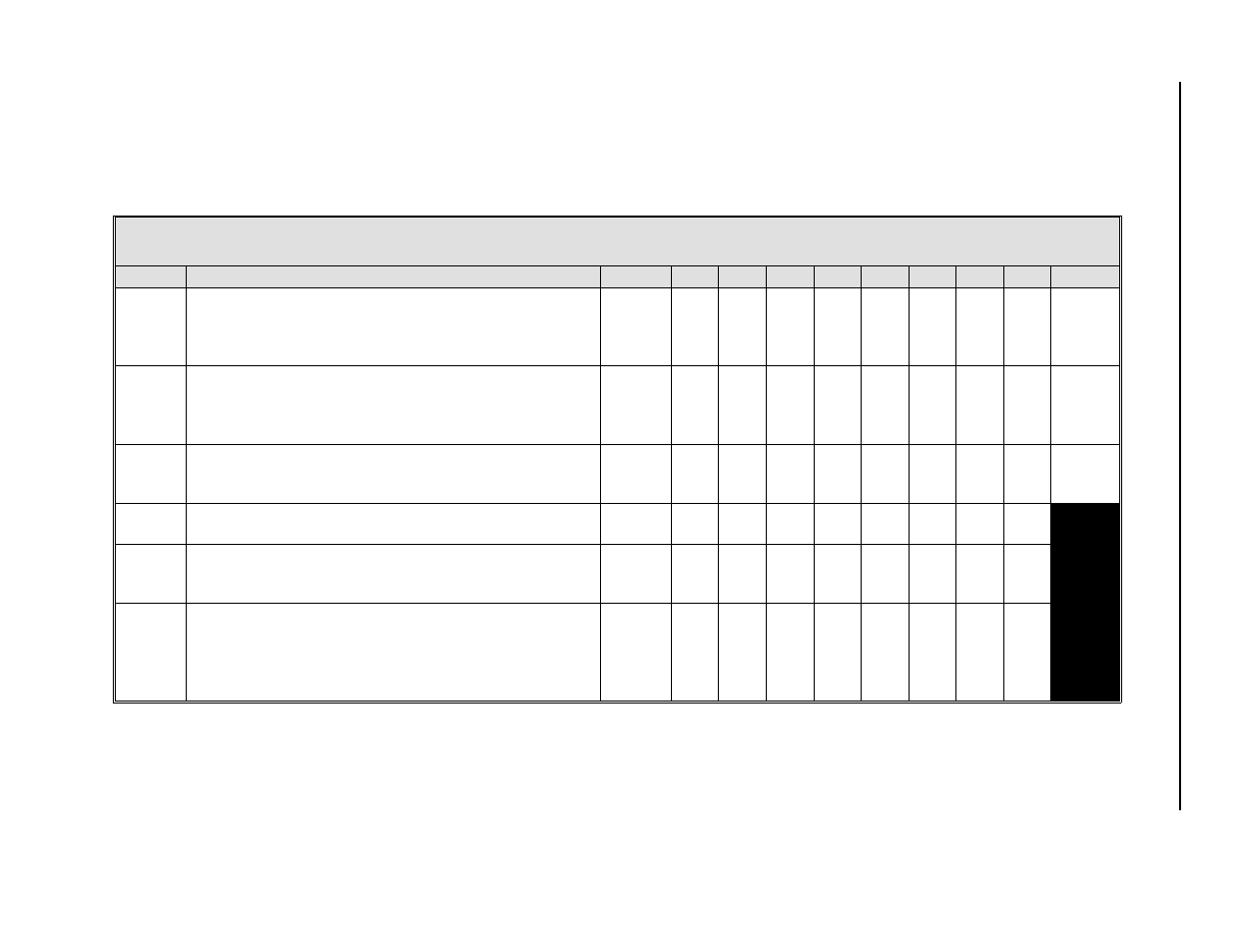
5.12 TREND MODULES
There are eight configurable Trend Modules that can be configured separately. Each Trend Module provides storage of the last 80 sam-
ples of the specified input (the last 40 samples are displayed on the point trend line). The first four Trend Modules are attached to the
CON Modules if the Trend Rate datapoint in the CON Module is non-zero. If the trend is attached to a CON Module, then height, rate,
mode, span, zero, and designator parameters are overwritten with values from the CON Module.
Table 5-12. Trend Modules
Title
Definition
Atom
0
1
2
3
4
5
6
7
Default
Trend
Rate
This parameter defines the recording rate in seconds
of the selected datapoint. Valid inputs are 1, 2, 3, 4, 5,
6, 10, 12, 15, 20, 30, and 60 seconds. A value of 0
turns off the trending.
TRR
(0-7)
B355 B358 B361 B364 B367 B370 B373 B376
0
Trend
Span
Samples outside this range are recorded at the limits.
When controlled by the CON module, values for these
datapoints come from the Controller Span and
Controller Lower Range.
TRS
(0-7)
C303 C305 C307 C309 C311 C313 C315 C317
0
Trend
Work
Area
This parameter is used internally by the controller.
TRW
(0-7)
H056 H057 H058 H059 H060 H061 H062 H063
0
Tag
A 10 character assignable name to identify each trend.
TAG
A072 A074 A076 A078 A080 A082 A084 A086
Trend
Eng
Unit
A 10 character assignable name that indicates the
units of measure which are being trended.
EU
A073 A075 A077 A079 A081 A083 A085 A087
Trend
Point
Desig-
nator
This parameter designates the datapoint to be
recorded. It can contain any L, B, C, or H datapoint
specifier. When controlled by the CON module, this
parameter is set to the PV (specified datapoint) of the
associated CON module.
TRP
(0-7)
F176 F177 F178 F179 F180 F181 F182 F183
5-
2
8
53
MC
50
00
P
ro
c
es
s
Co
nt
ro
l S
ta
ti
o
n