Micromod Micro-DCI: 53MC5000 Multi-Loop Process Controller Instruction Manual User Manual
Page 67
2.8 SIGNAL CONNECTIONS TO STANDARD REAR TERMINAL BOARD
Under ideal conditions shielded cable may not be required; however, in noisy locations two-wire
shielded signal cable should be used. Also, signal transmission distance must not exceed the limit
specified for the particular transmitter (refer to the applicable technical literature provided with the
respective device), and correct polarity must be observed when connecting remote transmitters to
the controller.
Each wire lead should be stripped to expose 1/4 inch (6.4 mm) conductor.
All wiring to the con-
troller rear terminal board screw lugs is supplied by the customer.
2.8.1 ANALOG INPUTS 0-3 (AI0-3)
There are provisions to connect four analog input signals (AI0-3) to the controller at the standard
rear terminal board. If the controller has the cord set terminal board option, the analog inputs are
connected to the Cord Set ITB. Each analog input can be configured for a two wire transmitter
(controller powers the loop) or a four wire transmitter (transmitter is self powered and does not re-
quire controller power). Controller power available to the transmitters is +24 V dc and is limited to
80 mA current maximum. The power available to the transmitters is net of the power required by
the controller itself (there is no separate power supply for transmitters). Each analog input signal
range is selectable either as 4-20 mA (1-5 V) or as 0-20 mA (0-5 V). (Selections for the analog in-
puts are provided in Section 5, Configuration Parameters.) When the input for AI2 or AI3 is a cur-
rent signal, a voltage dropping resistor that is 250 ohm (
±
0.1%) must be installed at the terminal
connector screw lugs with the input wires for that AI. The resistors for AI0 and AI1 come installed
on the rear terminal board as illustrated in Figure 2-23. If the input is a voltage signal for AI0 or
AI1, then the appropriate resistor (
R1 for AI0 or R2 for AI1 ) must be removed from the terminal
board. The Cord Set ITB has all four resistors (
R1 through R4 ) for AI0 through AI3 which elimi-
nates the necessity to add a resistor for AI2 or AI3 current input signals.
An overall illustration of the controller rear terminal board with signal definitions is provided as Fig-
ure 2-24. Figures 2-25 through 2-28 illustrate shielded two-wire current input signal connections to
AI0-3 from self powered transmitters and from transmitters that require controller power. Figure
2-29 contains a graphical illustration of AI signal conditioning.
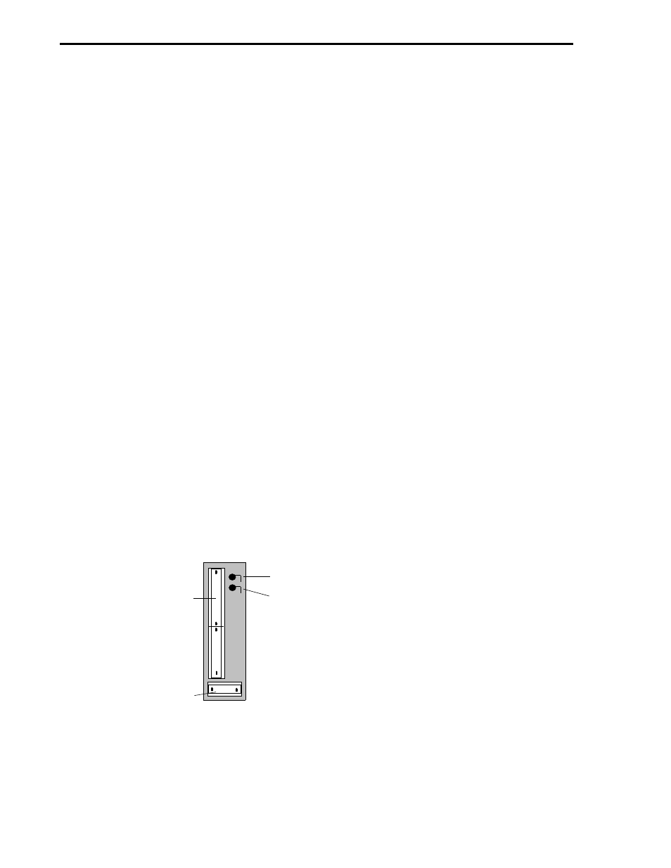
Figure 2-23. Rear Terminal Board Resistors R1 and R2
R1
R2
R1 AND R2 ARE 250 OHM
±
0.1% RESISTORS
MOUNTED VERTICALLY ON
REAR TERMINAL BOARD.
THEY CONVERT THE AI0
AND AI1 INPUT CURRENT
SIGNALS TO VOLTAGE
DROPS. EACH RESISTOR IS
REMOVED IF ITS INPUT IS A
VOLTAGE SIGNAL.
BACK OF REAR TERMINAL BOARD
TB1
TB2
53MC5000 Process Control Station
2-28