Table 4-6. status indicator display modes – Micromod Micro-DCI: 53MC5000 Multi-Loop Process Controller Instruction Manual User Manual
Page 140
4.7 DISPLAYS 21 AND 22 - DISCRETE STATUS DISPLAYS
There are two Discrete Status Displays, SDT0 and SDT1, that show the current state of sixteen
logical parameters in the controller (eight parameters per display - see Figure 4-12). Each of the
logical parameters has a dedicated set of configuration bits that determine how the status indicator
appears on the display, whether or not an alarm will be generated when the indicator is active, and
if operator/control mode access is permitted to alter the parameter state with the F3 push button.
The individual parameters of a display are selected with the setpoint up/down push buttons.
The Mode (M) bit indicates how the status indicator is displayed, which is also affected by three
other parameters: SDT Alarm Enable (A), SDT State (S), and SDT Alarm Acknowledge (K). De-
pendent upon the contents of all four of these datapoint types, the status indicator can be dis-
played as 10 characters (10), the first five characters (1-5), or the second five characters (6-10).
(First five and second five character display modes are used to simulate the functions of push but-
ton switches.) Display modes include normal video, reverse video, flashing video, or flashing re-
verse video. The F3 push button can toggle the SDT State bit if the corresponding Modify Disable
datapoint for that status indicator in the display is set to 0. If the Modify Disable datapoint for that
status indicator legend = 1, then modification to that status indicator is inhibited. The selection
pointer skips over inhibited status legends on the display; therefore, the F3 push button can not be
used to toggle the SDT State bit. (See Table 5-10, Status Display Modules, for all SDT0 and SDT1
datapoint definitions. Also, it should be noted that for the 10 control strategies presented in this
manual, STD0 is designated as a display only status screen and STD1 is designated as the opera-
tor input screen.)
The R/L, A/M,
⇐
, and
⇒
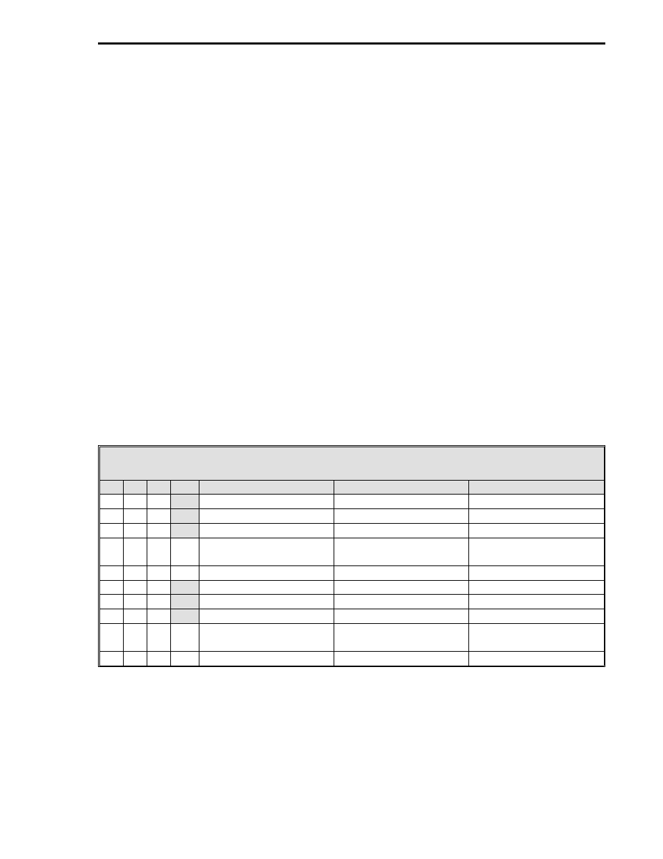
push buttons are not applicable for this display. The number of charac-
ters displayed for a status indicator, given the contents of the four parameters (MASK) is provided
in Table 4-6.
Table 4-6. Status Indicator Display Modes
M
A
S
K
Normal Video
Reverse Video
Flashing Video
0
0
0
1 - 10
0
0
1
1 - 10
0
1
0
1 - 10
0
1
1
0
1 - 10
(Reverse Video)
0
1
1
1
1 - 10
1
0
0
1 - 5
1
0
1
6 - 10
1
1
0
1 - 5
1
1
1
0
6 - 10
(Normal Video)
1
1
1
1
6 - 10
Notes: M = SDT Mode 0-7, A = SDT Alarm Enable 0-7, S = SDT State 0-7,
K = SDT Alarm Acknowledge 0-7.
Section 4. Operator Displays
4-27